

With the entire engine/propeller package likely to turn out much lighter than an O-360 and C/S metal prop, I decided to fabricate the new manifold out of mild steel. In practical terms the steel is only slightly heavier than aluminum and has several advantages from a welding and fabricating standpoint as well as being easier to obtain the materials and being less expensive. Steel also gathers less heat inside a hot cowling, reducing hot start and heat soak problems. Design considerations were cowling and alternator clearance plus getting the primary tubes the correct length to boost torque in the 4500 rpm range. Tube diameters were selected for maximum velocity to boost torque without sacrificing top end power. The plenum had to have sufficient volume and diameter to offer easy airflow to the runners and mount the stock 60mm throttle body. Provisions were made for air temperature and MAP takeoffs for the EFI system.
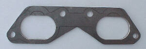
Head Flanges
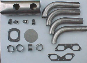
Using the intake manifold gaskets as patterns, I marked the outlines on 3/16 mild steel plates. Port holes were cut with a hole saw, although a plasma arc would be faster. These were cut oversize to allow for the runner tubing wall thickness.
Throttle Body Flange
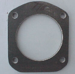
The T/B gasket was used to mark the pattern on 1/4 mild steel plate. A 2.5 inch hole saw was used for the main hole and the bolt holes were threaded for 5/16 NF bolts.
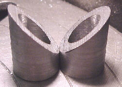
Intake Runners
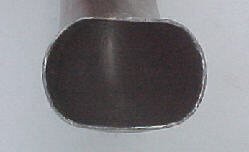
These were fabricated from 1.75 inch OD .058 wall mandrel J bends in a 4 inch centerline radius. I made several special tools to quickly form the oval shape at the head ends of the runners to match the intake ports.
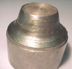
Velocity Stacks
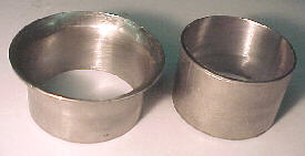
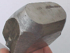
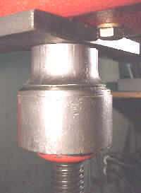
Velocity stacks to go on the end of the runners were shown to improve airflow by 19% on the flow bench over straight tubes. These were formed over a machined steel die in a hydraulic press by greasing the die and the short piece of tubing.
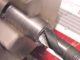
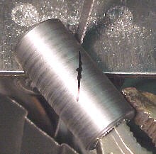
Injector Bosses
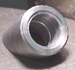
These were machined out of 1 inch OD, 1/2 inch ID DOM tubing and cut at 45 degrees on a bandsaw. O-ring retaining grooves and counter bores for injector clearance were also done in the lathe.
End Cap
The front end cap was cut out of .050 plate stock on the bandsaw.
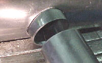
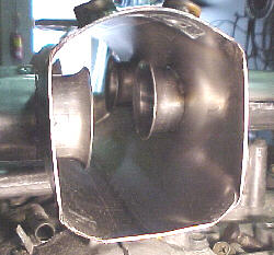
Plenum
The plenum was made from a piece of 4 inch, .065 wall, ERW exhaust tubing. A 1.75 inch hole saw was used to put the runner holes in it. The throttle body end was hammer formed to the shape of the T/B flange.
Construction
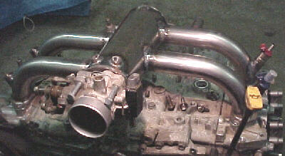
The first step to putting it all together was to TIG weld the stacks to each runner. The stacks must be installed in the plenum first. With that done, the whole assembly was carefully jigged up on the engine with intake flanges bolted down. Everything was carefully tacked and them re-measured. I then welded as much as I could comfortably reach from the top. The rest will be welded off the engine.
Injector Boss Fitting
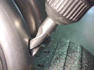
Injector boss centerlines were carefully marked on the intake runners, punch marked and pilot drilled with a 3/32 drill. These holes were progressively enlarged to 1/2 inch. With a 1/2 inch drill, the holes were elongated to match the injector angle in the runner by standing the drill up. The hole was then slightly enlarged with a 3/8 rat tail file and deburred with a flap wheel.
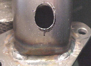
I made a fixture to hold the bosses parallel to each other and at the same depth. This fixture spigoted into the injector boss bores so that the top of the bosses were flush. Making sure that everything was lined up, I tacked the bosses in place, rechecked injector clearance in the bores and runners and put a second tack across from the first. The bosses were then TIG welded completely around.
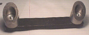
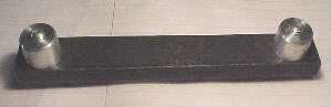
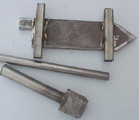
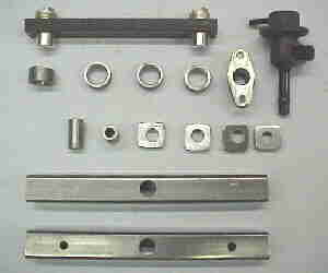
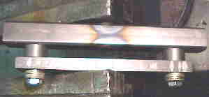
Fuel Rail
The fuel rails were constructed from 3/4 square steel tubing. End caps were 1/4 plate, injector spigots were machined from 1 inch OD, 1/2 inch ID DOM tubing. I machined a spigot jig to ensure proper spacing and squareness of the spigots on the rail while TIG welding. The stock EJ22 fuel pressure regulator and flange were used.
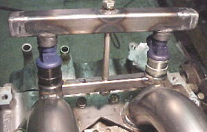
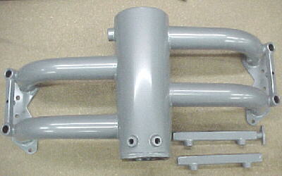
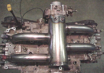
10/14/99 Intake manifold and fuel rails after powder coating