

Suzuki G13 Hall Sensor and Magnet Installation
The Racetech G13 Hall sensor kit is available to fit engines using both the reduced size Air Trikes aluminum crank pulley or a stock cast iron G13 pulley which is machined down. The Hall sensor mount is reversible to accomodate the two pulley diameters. Two paper templates are supplied which are used to punch mark the magnet holes for drilling.
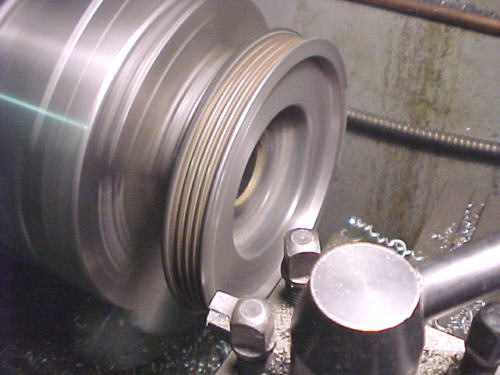
Stock Pulley Machining
If you are using the OE pulley, the front belt sheave must be machined off in a lathe. Machine the front face off flat until the pulley measures .725 thick at the belt grooves. The magnets will be placed into the front face.
Initial Setup
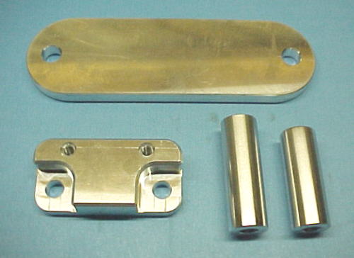
For either pulley, we need to first set the engine up at TDC. Align the arrow with the mark on the crankshaft belt sprocket. Bolt the crank pulley in place with 2 bolts, being careful not the turn the crankshaft. Remove the two 6mm bolts from the oil pump housing which straddle the unused 8mm hole. If using the OE pulley, bolt the Hall sensor mount to the oil pump housing using the bolts, lock, flat washers and standoffs supplied as shown in the photos below. Note on the OE pulley only, two thin aircraft washers are inserted under the standoffs. Two different length bolts and standoffs are used in both cases (supplied).
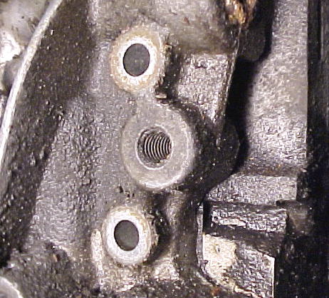
6mm bolts removed from oil pump housing
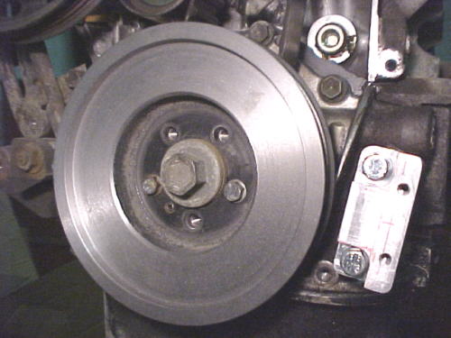
OE pulley in place and mount orientation
Air Trikes puley in place and reversed mount orientation
Now loosely bolt the Hall sensor to the mount using the 10-24 Allen bolts and stainless washers supplied. The sensor should be close to perpendicular to the mount.
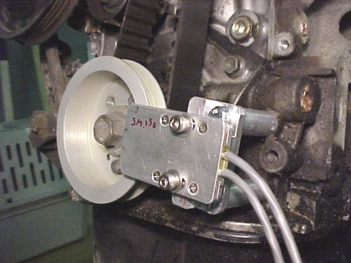
Air Trikes pulley shown in place with Hall sensor, mount and standoffs.
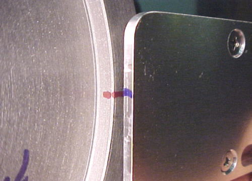
Use a sharpie marker to mark the pulley where the blue line on the sensor intersects.
While the pulley is bolted on, you may wish to put a new timing mark on the pulley as the factory plastic timing cover is usually discarded. For the OE pulley, the sharp edge of the belt tensioner can be used as a reference. For the Air Trikes pulley, the TDC arrow can be used as a reference. These marks will be needed to later calibrate the ECU for ignition timing.
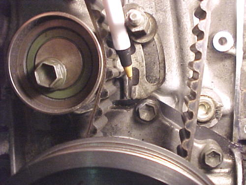
Using tensioner bracket as ignition timing reference for OE pulley
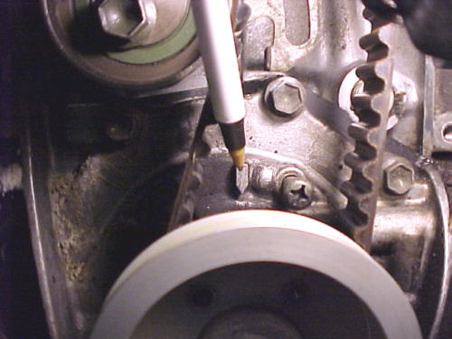
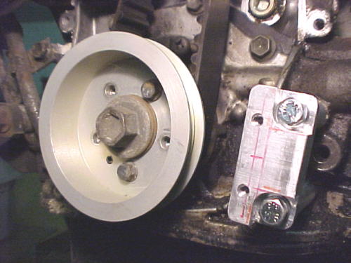
Using TDC mark as ignition timing reference for Air Trikes pulley
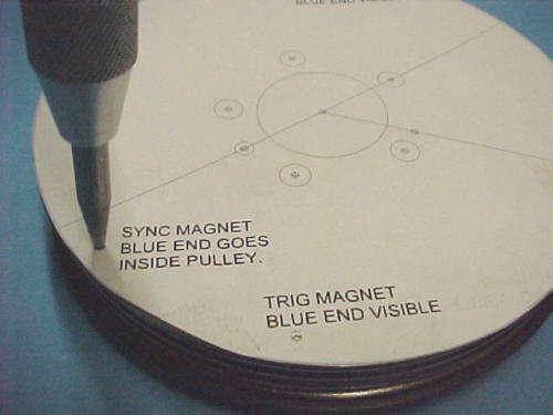
Remove the sensor and pulley. Cut out the paper template to suit your chosen pulley. Trim with sharp scissors as close to the line as possible. Place the template on the pulley accurately centering it and lining up the hall sensor mark made previously with the Hall mark on the template (see red marks on last two pulley photos). Carefully tape the template in place, again checking that it is centered. Using a mechanical center punch, mark the three magnet positions by punching through the template into the pulley.
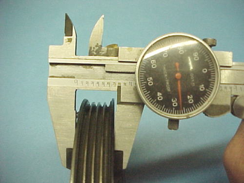
Remove the template. Take the pulley to a drill press and carefully center a 1/16 drill over the punch marks. Drill into the pulley slowly, no more than 1/16 (.0625) deep on all three holes. Change to a #30 drill bit. Carefully drill deeper. Frequently check depth of the hole by inserting a magnet into the hole after blowing the chips out of the hole. For the OE pulley, we want the magnets to protrude .070-.075 inches as measured with a caliper. On the Air Trikes pulley, we want the magnets to protrude .060-.065. Be very careful, especially with the OE pulley. If you drill too deep, you will break through into the belt grooves! Once satisfied that the mags protrude the proper amount, blow all chips off the pulley and out of the holes.
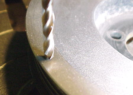
Final drill the pulley with #30 drill
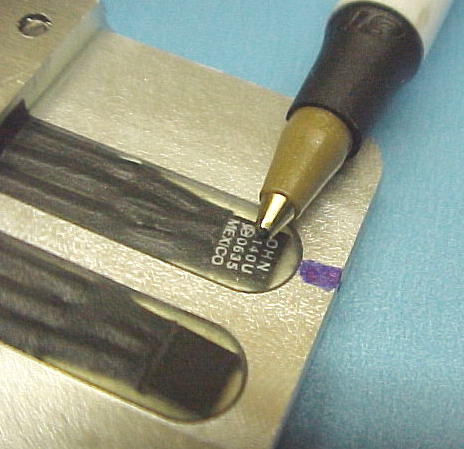
You are now ready bond the magnets into the holes. Use a 5 minute epoxy such as Devcon, LePages etc. Using a thick epoxy like JB weld is not recommended as it will trap air in the holes, making the magnets want to pop out. Using a piece of 1/16 welding rod or similar, put a small amount of epoxy into each hole (about half fill the holes). The blue end of the magnet must face out on the two trigger magnets located directly opposite each other. The single synch magnet must be bonded in with the blue end facing into the pulley. Push the magnets all the way into the pulley with the edge of your thumbnail or a non-ferrous object. Ideally, a slight miniscus of epoxy should form around the magnet as shown below.
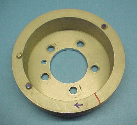
Air Trikes pulley with magnets mounted. Red line denotes trigger Hall sensor position at TDC.
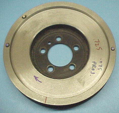
OE pulley with magnets mounted. Red line denotes trigger Hall sensor position at TDC.
Aligning the Sensor and Checking Air Gap
Bolt the pulley onto the crankshaft, install your fan belt and bolt the Hall sensor onto its mount, leaving the Allen bolts slightly loose. Slowly rotate the crank by hand watching for a magnet to approach the sensor. We want to see .040 to .080 clearance (air gap) between the sensor face and magnet faces. If too close, thin washers can be inserted under the aluminum standoffs. Most OE pulley installations require the thin washers supplied. The magnets need to pass over the center of the small black squares of the sensor visible through the epoxy coating. With the Hall sensor plugged into the ECU and programmer powered up, rotate the crankshaft by hand slowly until the magnets approach the sensor. With the programmer in the MAGNET window, watch for a change from NOT SEEN to SEEN as a magnets pass over. The upper screen is for the trigger magnets, lower for synch. By moving the pulley back and forth over a magnet, we want the magnet to remain SEEN for 3-4 degrees of pulley rotation. Adjust the Hall sensor in and out on its slots until this is achieved. This ensures that the magnets are aligned over the center of each Hall Effect element. In one complete revolution of the crankshaft, the trigger window should show SEEN twice and the synch magnet once. LOck the Allen bolts down tight now. The engine will never run correctly unless the magnets are seen properly by the sensor and ECU so this is a critical step. If you remove the belt, you'll have to realign the sensor again.
Magnets must spin over center of Hall Effect elements