

Basic SDS Tuning Guidelines for Aircraft Applications
This article is intended to be used in conjunction with the SDS Installation and Tuning Manuals which contain more detail. You should first become familiar with all the different programmable parameters by reading the main and supplemental manuals, available here: http://www.sdsefi.com/program.html
The primary focus of this article is to make people aware of the general process of tuning the fuel delivery and spark timing for automotive engines used in aircraft, so that these engines retain their mechanical integrity running at high, continuous power levels.
Background Technical Information
Air/ fuel Ratio
In most spark ignition, internal combustion engines, the mixture is combustible within an AFR (air/fuel ratio) range of roughly 9 to 1 to about 17 to 1. 9 being very rich, 17 being very lean. 14.7 is the stoichiometric ratio (chemically correct) for lowest emissions. Best power is obtained at around 12.5 for most naturally aspirated engines.
Pistons
Most automotive engines produced today have cast aluminum pistons as opposed to forged aluminum pistons used in race applications where engines produce high continuous hp levels. Forged pistons transfer heat much faster than cast ones and retain their strength at higher temperatures however, the increased fitting clearances required makes them an unattractive choice for production car engines where noise, emissions and longevity are important and the average hp is relatively low in the automotive application. Aluminum loses approximately 50% of its strength at 400F and this is a pretty typical temperature for a piston crown operating at medium to high power settings. The strength rapidly diminishes above 500-550F so they cannot be allowed to get this hot or deformation and fatigue will set in due to the high pressure they are subjected to. In other words, they can become somewhat plastic and weak if they get too hot.
Pistons are usually the first parts to fail from excessive thermal loads on automotive engines. The solution to this for almost all auto OEMs is to run the AFR very rich at WOT (wide open throttle) and high rpms corresponding to high hp output. The excess fuel drops the combustion temperatures, EGTs and cools the piston crowns themselves, keeping them within their safe thermal limits. While best power is obtained with AFRs around 12.5, most OEMs run the AFRs at between 10.5 to 11.2 at WOT. This is where you need to tune your AFRs also. While there will be a slight hp loss and you'll use more fuel, this is the only way the pistons will survive for very long running at continuous high power settings. I suggest a nominal target of 10.5 to 11.0 for power settings above about 75% and no leaner than 11.5 from 50% to 75% power. I'd also mention that detonation is most likely to happen at AFRs of around 12.5 as well if there is excessive spark timing and/or low octane fuel.
Valves
Automotive engine valves and seats vary in material and quality between engine types and brands. Again, these parts have thermal limits and high EGTs can decrease the life of these components. Rich mixtures decrease EGTs and exhaust valve temperatures. While most valve failures are slow and gradual compared to piston failures, we don't want degradation here either.
Detonation
The fuel/air mixture normally burns at a uniform rate within the combustion chamber however if the rate of pressure or temperature rise becomes excessive, detonation can occur. This is the spontaneous explosion of the remaining mixture sometime after the spark event occurs. The result is a rapid and excessive pressure and temperature rise within the chamber, which can often lead to broken ring lands on the piston. Some engines can withstand light or moderate detonation for many hours, some can't. Subaru engines don't take detonation very well. Heavy detonation is like hammer blows on top of the piston and most production engines won't take this for more than a few seconds at a time under heavy detonation. Having the ignition timing too far advanced for the fuel octane is the leading cause of detonation, running the AFR too lean also contributes to detonation. You are not likely to be able to hear detonation over the noise of the propeller and exhaust in an airplane so we must program the ECU so that detonation cannot occur in the first place.
Pre-ignition
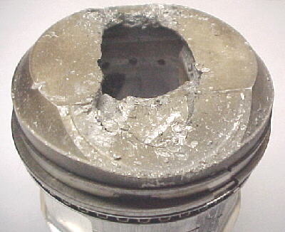
This happens when there is a hot spot somewhere within the cylinder which raises the temperature of the mixture above its autoignition temperature. This happens before the spark is initiated, leading to a massive temperature and pressure rise before the piston reaches TDC . Most of the heat and excess pressure goes into the piston. Within the space of a few seconds, the piston will simply melt in the middle, the pressure caving in the crown and melting the spark plug electrode off. You cannot hear pre-ignition at all and failure is virtually instantaneous in all cases.
Burned Pistons
We have a third condition where there is no detonation or pre-ignition present and this is caused simply by excess temperatures on the piston crown, almost always caused by running too lean for too long. In this case, the piston reaches a temperature where the structure of the crown and upper ring land distorts and deforms under the combustion pressure. In minor cases, the upper ring is pinched in its groove leading to a mild compression loss. In more serious cases, one edge of the piston (usually near the exhaust valve side) will melt, collapse or break off leading to a major compression loss and possibly even major damage to the chamber as the broken parts slam into it. There is no warning to this type of failure and it's slow and insidious. Many engines will last 20-75 hours before succumbing to this type of failure, showing few outwards signs with compression loss or higher oil consumption. I have also seen failures like this in as little as 3 hours of flying time. It depends a lot on how overheated the piston runs and for how long. I should also mention that excessive coolant and oil temperatures do no favors to dissipating extra heat from the pistons. Exceeding 220F on either of these regularly isn't helpful.

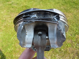
I have seen all 3 of these types of failures happen in automotive engines and any of them are going to spoil your day. As you can imagine, as soon as the piston no longer seals due to damage, there is a compression and power loss and usually excessive blowby, leading to oil being pushed out the crankcase breathers. Left long enough, the engine will run out of oil and seize. As the combustion gases leak by the piston and rings, erosion and melting accelerates as you can see in the second photo above.
Now that the scary stuff has been discussed, we can get into the meat of proper ECU programming to try to prevent these things.
Magnet Position Value
First item to check is the magnet position value. Read the appropriate section in the SDS F Supplement Manual to fully understand this. Basically, this is a one time calibration to the ECU to correct displayed ignition timing with actual ignition timing on the engine. You must connect a timing light to the #1 plug or coil wire and have a mark on the crank pulley for TDC or 10 degrees BTDC. On engines like the EZ30 with COP (coil on plug) ignition, you may have to get a short piece of spark plug wire to put between the coil and spark plug to be able to attach the inductive pickup for the timing gun to temporarily or in some cases, you can try the inductive clip on the coil trigger wire. Use a dumb timing gun without an adjustable knob on it. (important)
If you have a TDC mark, set the rpm ignition timing in the programmer to 0 at 1250, 1500 and 1750 rpm. If you have a 10 degree BTDC mark, set the rpm ignition timing to 10 at these three rpm ranges. Start the engine (mindful of the propeller!) And set the throttle to get an idle at 1500 rpm, confirm in gauge 1 mode. Scroll right until you get to the Magnet Position Parameter. The default value is 80 for magnet position. Check your timing mark with the gun. If your timing is the same as what you have set in the ECU, no adjustment to Magnet Position is required. If the timing does not agree, change the setting by using the +1 or -1 buttons to increment or decrement the 80 value until actual timing matches your programmer timing value at 1500 rpm. A change of 1 will change ignition timing 1 degree. Once Magnet Position is set, whatever you enter for rpm ignition timing will be correct as long as you don't move the Hall sensor. You may now reset your rpm timing values to whatever you desire.
If you don't verify that the magnet position is correct, you really don't know if your actual ignition timing is correct so you could have more advanced timing than you think, which can lead to detonation.
Ignition Mapping
On the Subaru EJ and EZ engines, best power is made at around 30 to 32 degrees BTDC on 100LL. Typically, ignition timing starts out on most engines at about 10 degrees BTDC from 500 to 1000 rpm and we'd increase timing about 3 degrees per 250 rpm step in the programmer until you reach around 30 at 2500-3000 rpm. The timing would stay at 30 degrees above this rpm all the way up to redline. In the case of the Subaru engines with their relatively high compression ratios, we've found that timing should be limited to around 25-26 degrees when running on 91 octane mogas so that detonation cannot occur. Timing may be fully advanced to 32 degrees in the case of running 100LL or a 50/50 mix of mogas and 100LL as there is no chance of detonation with this higher octane fuel. I would not run less than 91 octane fuel in these engines as it would require even less timing which raises EGTs and reduces power even more.
On the SDS, we have two parameters affecting ignition timing- RPM IGNITION and IGN RET- ADV/ LOAD. Total timing is the composite of these two figures- RPM timing plus or minus the MAP retard or advance value. For simplicity on naturally aspirated engines, we usually just use the RPM IGNITION values. It's possible for advanced users to also use the IGN RET- ADV/ LOAD parameter to advance timing at low manifold pressures (MAP) and retard it at high MAP to possibly obtain higher cruise efficiency. If you want to try this, read the appropriate section below . On naturally aspirated engines then, IGN RET- ADV/ LOAD values can all be set to 0 so they don't affect total timing.
One anomaly to note on the Eggenfellner setups is that very advanced timing values are entered at low rpms. Timing is set at around 28 degrees to help minimize severe propeller kickback when starting the engine. This is caused by a torsional vibration period between the engine, gearbox and propeller at around 350 rpm. The engine seems to start ok with this much initial timing but it may look odd to many people. You probably need to leave those timing values they way they are here. The ECU uses the timing value at 500 rpm for every rpm up to 500.
Typical timing on the EZ engines can look something like this on 91 octane fuel:
RPM Timing Value
500 28
750 28
1000 12
1250 15
1500 18
1750 21
2000 24
2250 25
2500 25
2750 25
etc.
MAP IGN RET- ADV/ LOAD Value
3.22 0
4.12 0
5.02 0
5.92 0
6.82 0
7.72 0
8.62 0
9.52 0
10.4 0
11.3 0
12.2 0
13.1 0
14.0 1A
14.9 1A
15.8 2A
16.7 2A
17.6 3A
18.5 3A
19.4 3A
20.3 4A
21.2 4A
22.1 3A
23.0 3A
23.9 2A
24.8 2A
25.7 1A
26.6 0
27.5 0
28.4 1R
29.3 1R
31.2 2R
On 100LL, you may increase the maximum timing to 30-32 degrees.
Fuel Mapping
You need to have a wideband AFR monitor installed to display and verify AFRs. Most mapping can be done with the aircraft chocked, brakes on and tied to a vehicle on the ground. Take suitable precautions when ground running at high power settings and watch oil and coolant temperatures, don't exceed limits here.
Once the engine is warmed up, AFRs are a composite of RPM FUEL values X MAP FUEL values with small corrections for intake air temperature. Since MAP values are usually a linear progression, we usually don't have to touch those values on naturally aspirated engines and most programming is done only on the RPM FUEL values. You should check your MAP values however and they should look something like the figures below for the EZ30 engines:
MAP Values
MAP Value
3.22 100
4.12 100
5.02 15
5.92 18
6.82 21
7.72 24
8.62 27
9.52 30
10.4 30
11.3 33
12.2 36
13.1 39
14.0 42
14.9 45
15.8 48
16.7 51
17.6 54
18.5 57
19.4 60
20.3 63
21.2 66
22.1 69
23.0 72
23.9 75
24.8 78
25.7 81
26.6 84
27.5 87
28.4 90
29.3 93
31.2 96
The 100s at low MAP are the defaults to keep the engine running in the event of a MAP sensor failure so don't change these. The values are around 30 in the idle range so the mixture does not hunt.
Do all programming with the mixture knob at 0% correction (straight up). This can be verified in Gauge 2 mode. Set the propeller to full fine pitch. Use the < or > button to scroll to the correct screen. Pressing the gauge button will take you to Gauge 1, press it again and it will take you back to whatever screen you were at previously.
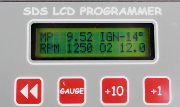
Gauge 4 screen showing important parameters, including AFR
RPM Fuel Values
On the EZ30 engines using standrad injectors and fuel pressure, your values might look something like this:
500 130
750 130
1000 130
1250 130
1500 130
1750 130
2000 130
2250 130
2500 130
2750 140
3000 150
3250 150
3500 150
3750 150
4000 155
4250 155
4500 160
4750 160
5000 165
5250 165
5500 165
5750 170
6000 170
6250 170
Our goal is simply to adjust the RPM FUEL parameter at each 250 rpm break point to obtain an AFR of around 12.0 to 12.5 up to 2500 rpm (idle and taxi range) and 10.5 to 11.0 at 2750 rpm and above. Get on the brakes and start the engine. Don't do any programming to RPM Fuel values until the engine reaches 150F coolant temperature. At each rpm, verify it's stabilized at each rpm break point in the SDS programmer (not the aircraft tach), check AFR, increment or decrement the RPM FUEL value using the +1 or -1 buttons until you get the desired AFR. Making the RPM FUEL value larger makes the AFR richer and vice versa. Note there will be some scatter in the readings so aim for a nominal reading. If you are trying to get 11.0, it's somewhat normal to see variations between about 10.8 to 11.2.
Keep increasing the throttle to increase rpm, stabilize and verify at each 250 rpm break point, check AFR, correct the RPM FUEL value to get desired AFR. Repeat. Go all the way up the rev range until you are at full throttle. You are done on the ground now, assuming the engine starts and warms up smoothly. If not, consult the manual on how to change the START and ENGINE TEMP parameters to get good hot and cold starting and warmup.
As far as the basic programming goes, you are ready to test fly. When in flight, keep checking the AFRs, if they are off quite a bit, you can temporarily fix with the mixture knob. You can note the trends and knob percentage required to correct the AFRs at certain rpms. You can correct these on the ground later. For example, if the AFR in flight is 12.0 at 4000 rpm and you want 11.0, take 12/11= 1.09. Multiply your RPM fuel at 4000 rpm by 1.09 and re-enter. If the value was 200 originally, change it to 218. This normally should not be required after ground running but the proof is in the pudding while flying.
Jan. 15/15 Service Bulletin Regarding Vertical Power VP-X and SDS
It has come to our attention that the VP-X electronic switching/ circuit breaker box does not use average current draw over several seconds to trip breakers like conventional thermal breakers do. It may trip during normal operation due to peak current transients over only a few milliseconds. This can lead the pulsing current of the ignition coils and injectors to trigger the breaker far below nominal current levels. We believe this could cause a serious flight safety issue and engine stoppage. Be sure to set the breaker values on the VP-X far higher than the nominal current draw on these circuits. Be aware that average current draw can increases with rpm and load so ground running may not allow complete testing of this condition if static rpm is lower than flight rpm and engine shutdown could occur in flight. Breakers are to protect the wiring, not the device. We recommend each 4 cylinder coil pack have a rating of at least 15 amps assigned when using the VP-X, each 6 cylinder coil pack at least 20 amps, 4 cylinder injector power at 15 amps, 6 cylinder at 20 amps and 8 cylinder at 25 amps. These are only recommendations, use this information at your own risk and these values should be thoroughly tested prior to flight at WOT and maximum rpm the engine will see in flight.
Ross Farnham