

Hobbs 424.4.3 hours
This page will detail the testing of all the modifications done to our RV6A over the Winter and Spring. I intend to instrument the radiator with inlet and outlet pressure probes, an exit velocity probe and exit temperature probe and eventually tuft test and video airflow patterns in flight.
May 5/13
Today I ran the engine for about 30 minutes with the propeller on and cowlings off to test cooling with the new rad seup, get impressions of the changes to the torsional vibration characteristics at lower rpms with the flywheel mods, test for oil drain back of the revised turbo system and do some engine break in under load. I ran the engine up to 4400 rpm. The engine is much tighter and turns over slower on the starter. It is hard to hold on the brakes now at 4400 and 35 inches MAP.
Cooling
New radiator setup
First impression is that warmup is faster with the thermostat installed and the smaller coolant volume now (about 2 liters less). At 1000 engine rpm (454 prop rpm) with the OAT at 18C, the coolant temp stabilized at 90C. Temp 2 or T2, measured at the water pump inlet, after passing through the rads, was 79-81C. I increased rpm to 1600 engine (727 prop) and the coolant temp fell to 80C, T2 to 73-75C. At 2000 rpm, coolant temp remained at 80C and T2 fell to 65C. Clearly cooling improves as rpm is increased over the standard idle speed of 1000 rpm. This was expected after flow bench tests of the rad core showing at low face pressures, very little air makes it through the core. T2 shows the delta that the rad provides. Note that coolant temp is measured on the SDS gauge head and just has 10C resolution on the hot end. Running was all done with the rad exit door fully open.
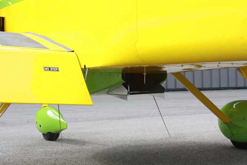
Rad door fully open
Torsional Vibration
With the addition of 8 lbs. of mass to the flywheel, doubling the previous inertia, TV was substantially reduced at the previous 2 bad rpm ranges (600 to 950 engine rpm and 1050-1600 rpm). I would guess amplitudes are up to 75% lower now here. I can operate the engine at 1200-1600 rpm now without the massive vibration and noise I had pereviously. Very happy about this! Perceived engine smoothness above 1600 seems unchanged.
May 6/13
I ran the engine on the ground for 45 minutes to test ground cooling with the cowling in place. OAT was 27C. I was facing into a 10 knot wind about 40 degrees off the wind direction. The test was started with the rad door closed and idle at 1000 engine rpm. At the 30 minute mark, water temp on the SDS was showing 90C. I then opened the rad door fully. After 5 minutes the other two water temp sensors fell about 5 degrees. Then I increased idle to 1600 rpm. Rad exit temps fell 5C more. I increased idle to 2000 rpm and after 5 more minutes, SDS water temp dropped to 80C and the other temps remained the same. Very happy that I could run under these ambient temps for 45 minutes with no overheating.
May 15/13
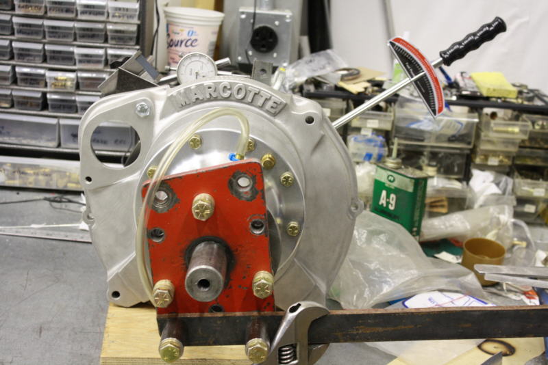
Ready to start ground running again after fixing (hopefully) a small but annoying oil seep from the gearbox which has crept in over the last two years. Seemed to be leaking through the bolt heads on the case. Unfortunately Marcotte appeared use red locktite on the threads and when I removed 2 of the bolts, the threads came with them. The holes were not tapped very deep and the casting is over an inch thick, so I was able to tap through and install longer bolts.
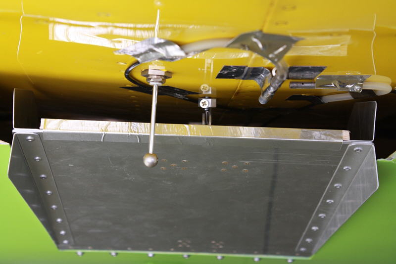
Now have pressure, velocity and temp probes temporarily installed to see what is going on in the rad duct. Flight tests to follow soon after some more ground running at high power.
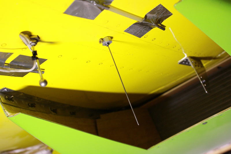
Pressure probe place in rad inlet
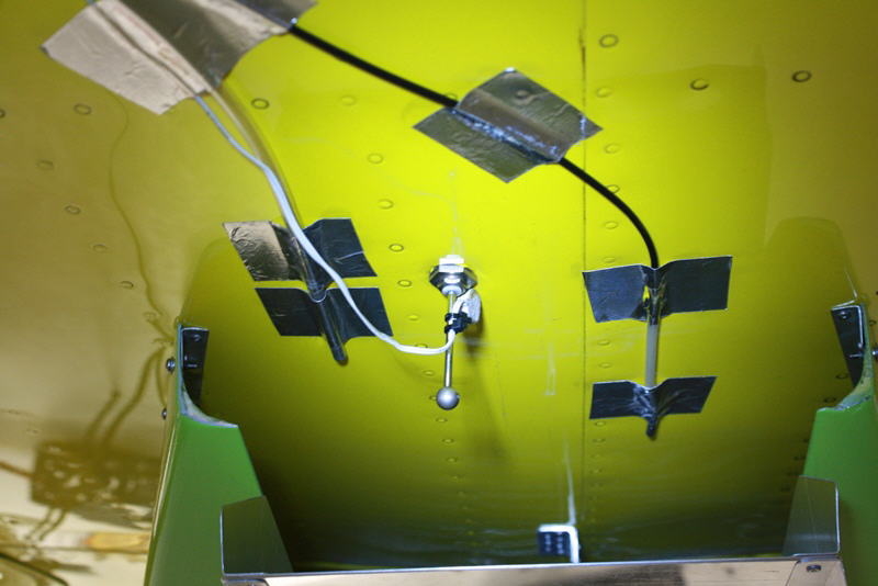
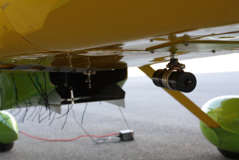
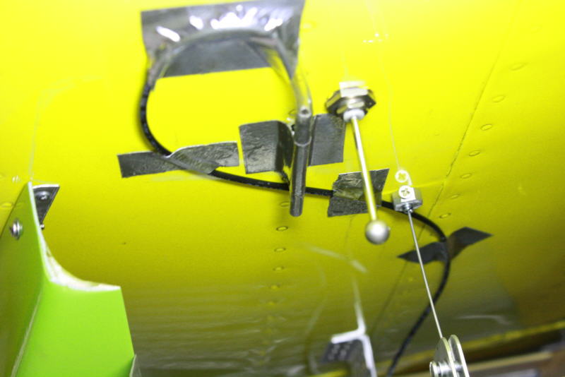
Velocity, pressure and temperature probes places in rad exit

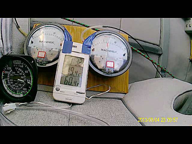
Velocity, inlet/ outlet pressure and temperature gauges in cockpit
May 16/13
Ground running again to check the rad instrumentation. OAT was 17C, ran for about 30 minutes. Coolant temp never exceeded 70C. Amazing compared to the previous setup. Seeing about 1 inch of water at the rad inlet at 2000 rpm. Radiator discharge temp got up to 68C. The interesting part was closing the rad door at 3000 rpm. The velocity went from about 25 knots with the door fully open to almost 40 knots with the door fully closed. Very cool and a first step to being able to recover cooiling air momentum and reduce drag in flight.
May 26/13
After solving some minor leaks and remapping the AFRs and ignition timing while doing full power ground runs, everything seems in order now to do the first test flight. Just waiting for some good weather now.
TV Testing
Back to the gearbox and torsional vibration studies. I have completed the calcs for the Marcotte M300 gearbox stiffnesses and mass moments of inertias for the various internal parts. Today I set up a rig to measure the torsional stiffness of the coupler bushings.

The bushings installed in the M300 drive plate
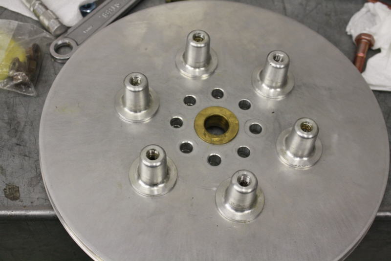
The drive pins on the flywheel
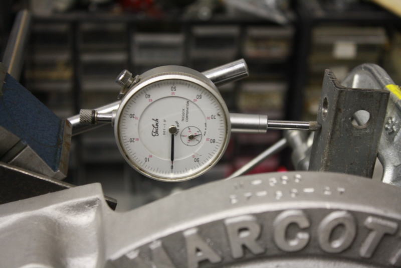
Dial indicator set up to measure deflection
Test rig to hold the prop flange steady and torque wrench to measure torque
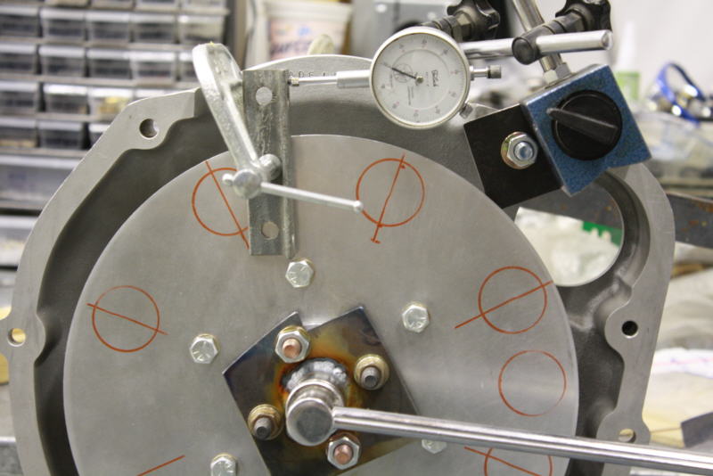
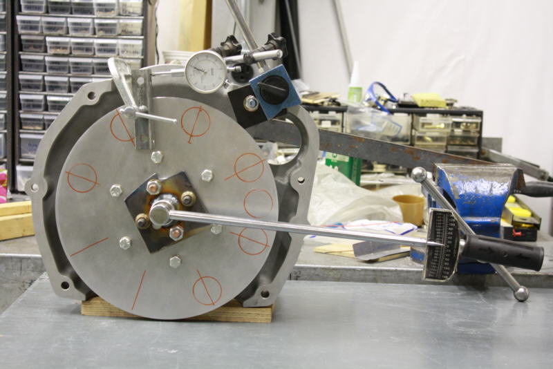
The results of the test at 15C shop temperature was 25 lb./ft./ degree. Much softer than I had surmised. This was the last piece of the puzzle before beginning to plug in all the numbers to the spread sheets.
First Test Flight
Yesterday I managed to fit in the first test flight. Cooling was good, never over 70C. The airplane seemed faster than before at the same power settings but maybe because I have not flown it for 6 months or maybe the engine is making more power or I actually have less drag. I didn't have much time to test and look at things. I had 5 inches H20 at the rad inlet at 100 knots IAS, 1 inch on the outlet with the door wide open. Had 50 knots exit velocity at 100 knots, door still open. All the other temps and pressures look good after review of the cockpit video. Ground running vibration far less than before with the new flywheel mods. Also happy the new turbo oil drain which seems to be working fine, glad to get rid of the electric scavenge pump and its weight.
Short taxi vid here: http://s1105.photobucket.com/albums/h341/rv6ejguy/?action=view¤t=MAH00012_zps0b3fb892.mp4
May 29/13
Checking over everything after the test flight. I am modifying the rad door actuation to make it stiffer. Looks like there are pretty big forces on it in flight, forcing it open.
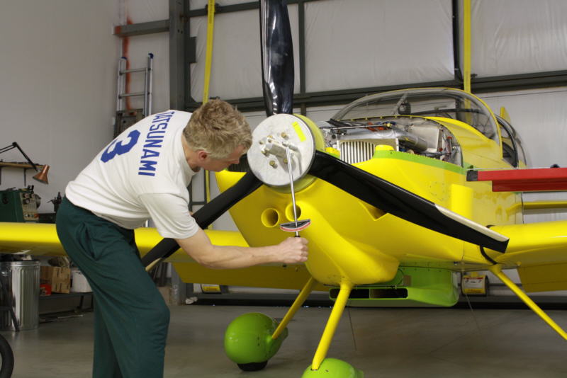
Checking torque on the IVO propeller bolts. This was the third check after a few hours running and the bolts took no torque this time so we are good to go again.
Second Test Flight, June 2/13
I got in a longer test flight on June 1. OAT was around +10C. Coolant temps stayed right at 70C for the whole flight except when I throttle way back to land where they fell down to 61C. Note there is a thermostat fitted with a .125 hole in the plate so the cooling is minimal from the main rad with the thermostat closed and only the heater core is flowing coolant. So cooling is very good with the new scoop setup.
Oil temps never exceeded 85C in the climb, 81 in level flight. Using one of the old rad feed ducts to blow directly on the pan.
The new front location for the intercooler is a lot better than before. Seeing a 40-46C delta now.
The new gravity feed turbo oil drain setup appears to be working fine. Glad to rid of the weight, electrical draw and single point of failure concerns with that.
Redrive temp never exceeded 45C. This is about 15C cooler than before. Using an old intercooler feed duct to blow on the redrive case now.
Results of the rad door tests so far: At 100 KIAS, seeing 5 inches inlet P, 2 inches outlet P, 50 knots exit V with door fully open. At 120 KIAS, door about half open, inlet P 6.5 inches, outlet P 4 inches, exit V 70 knots, exit temps around 34C. The door is hard to close and I am not sure if it is springing open in flight more from the air loads. Need to investigate that further. So far, the ventral rad setup seems vastly superior to the buried rad concept.
The crankcase breather is totally dry after flying now, showing that the ring seal is very god again after the rebuild. No more black streaks!
Intial results seem to say the airplane is at least 5 knots faster than before at similar power settings. This may be either due to the engine being fresher or an actual reduction in cooling drag or both. Either way, more speed for the same fuel is better.
The new heavy flywheel is smoother everywhere below 1600 rpm and allows me to taxi now down to 1300 rpm. Very happy with that change. Mathematical analysis showed F1 to be at 615 rpm which feels about right from seat of the pants. The other bad predicted period is at 27,000 rpm so maybe we are in a happy place now.
The dynamic coolant air bleed from the top of the engine water crossover pipe to the top of the coolant fill tank works perfectly. Most air bleeds out when filling the tank and by running the engine for one minute, the system is completely purged of air. Highly recommended for any Subaru installation.
June 6/13 Torsional Vibration Analysis
With help from Dan Horton, I completed the the math analysis of the current and past combinations of engine, flywheel, gearbox and propeller using a Holzer 4 element model. With the new setup, M300 gearbox, IVO prop, and 16 lb. flywheel- Omega 2= 129 rad/sec. 20.5hz (615 rpm) Displacement vector here was -8.91. This seems to agree very closely with what I can feel as far as the predicted rpm range. The next harmonic range is predicted to be over 27,000 rpm so this is way above the operational range. With the idle set at 1000 rpm, I am fairly confident now that I won't break anything in the gearbox at least from TV.
Have had some radio problems lately. Spent last night trying to solve these before I can fly again.
June 8/13 Flight Test
This flight was cut short with radio problems. I took off with the rad door closed and temps didn't exceed 80C in the climb with the OAT at 21C. About all I could observe was that the rad exit velocity was about 85% of the airspeed with the door closed and delta P was only about 0.5-1 inches H2O different. I need to get these radio problems solved so I can properly compile the data.
July 30/13
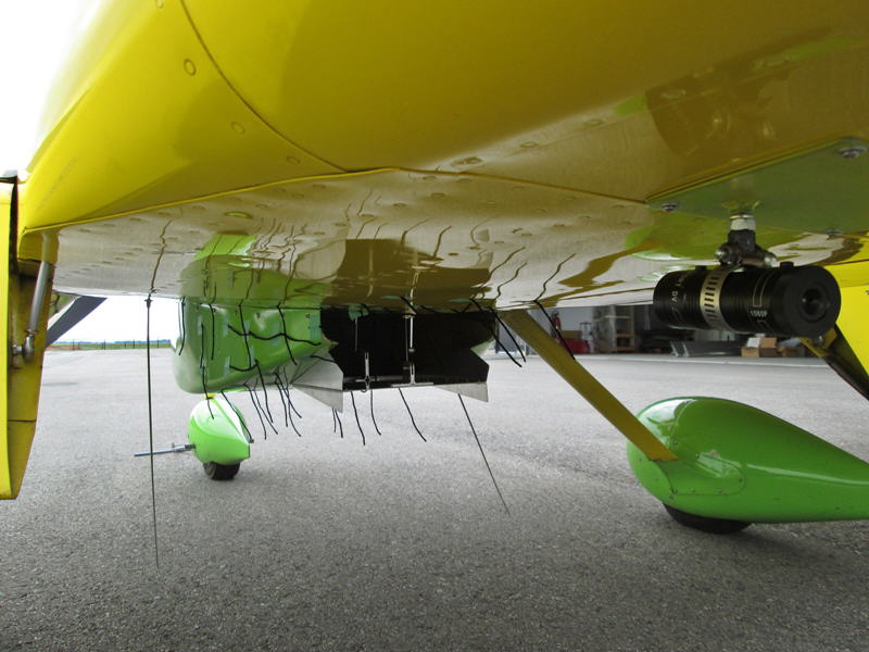
Haven't updated for a while with trips to Asia, a wedding and fixing the radio problems plus a crank sensor issue. I did a short flight on the 28th and finally both radios are 5 by 5 and the engine is running well. Now the internal GPS battery is dead so it will be a few more days before I can get that fixed. I'll have a video camera installed on the belly to look at the rad door in flight plus I've tufted the rad scoop and door exit area to look at airflow patterns there. Hopefully soon I can collect the rest of the performance data.
Video camera to record rad tufting and door position in flight
Aug. 11/13
I got flying a couple days ago after waiting for decent weather. The video showed the exit door was indeed springing open in flight from the air loads so I'm now redesigning the actuation mechanism.
http://www.youtube.com/watch?v=QT8njoirTkU&feature=youtu.beAug. 14/13
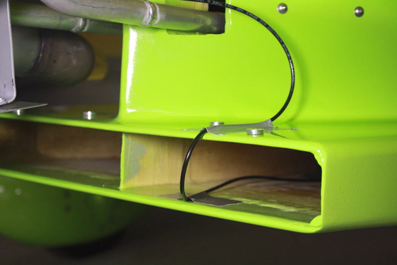
Got the new door mechanism designed and installed
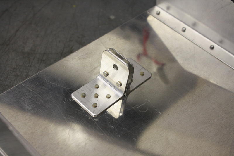
New cable attach point at aft end of the door
Cable exits the belly vertically now for more direct pull force
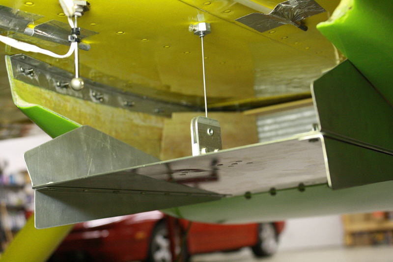
Door and cable in place
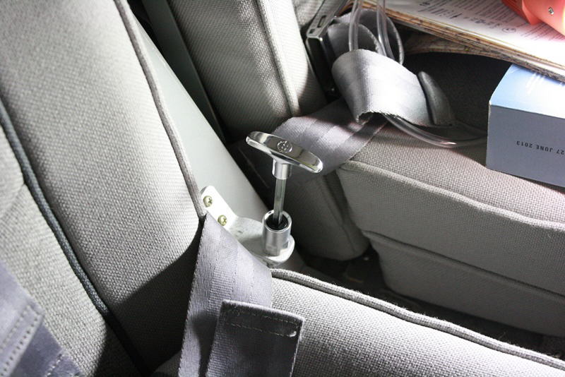
Coockpit control for rad exit door is a 90 degree, twist to lock, push/pull cable
Aug. 18/13
I did flight testing yesterday with video cams in the cockpit to record the instrumentation.
Screen shot from video cam in flight

Basic pressure, temperature and velocity data
It's clear from this, we can get very high heat transfer rates from radiators compared to air cooled engines despite much lower Delta T and that the properly ducted radiator with variable geometry exit door can recover substantial cooling air momentum compared to other poor designs often used in experimental aircraft. Depending on speeds, coolant temp and door position, we are recovering 59-96 of the original velocity at the duct exit. So yes, the Meredith Effect is real. With higher coolant temps, even at low speeds like this, I believe we can reach velocity parity and perhaps even a bit of net thrust.
We are seeing peak radiator efficiencies of 92%. This is much higher than air cooled engines which are showing around only 50% in similar flight testing.
Ram recovery peaks at 84% on this scoop design- pretty darn good as well
The next study will try to look at duct inlet airflow in flight if I can figure out how to get a cam mounted...
Aug. 21/13
I went flying again with the cam on the nose gear leg looking back at the rad scoop with tufts.
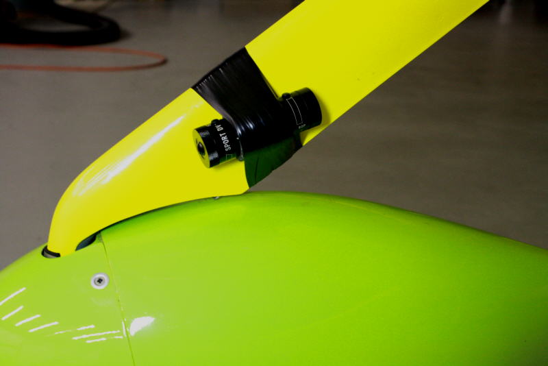
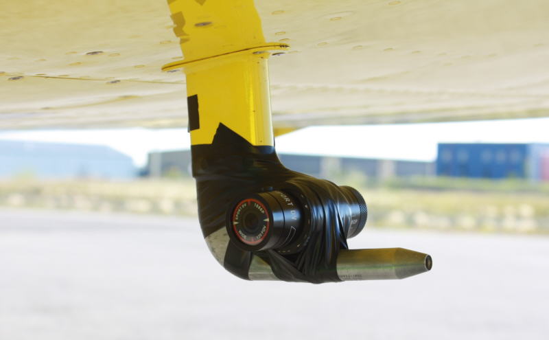
$60 Chinese sport cam taped to gear fairing
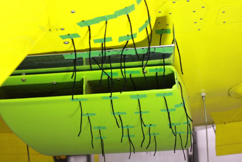
Tufts on rad scoop
New rad pitot tube installation in now plumbing internally and spaced .25 off skin to get it out of the boundary layer for more accurate results.
Here is the video:http://www.youtube.com/watch?v=gPpWHvr1kJw
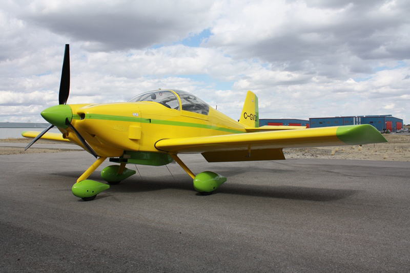
Here is a general information video on the RV6A: http://www.youtube.com/watch?v=wPtuUZzm3Cs
Aug. 26/13
I was up again on Saturday to do some more tuft test video on the scoop: http://www.youtube.com/watch?v=xqG0QcHpL5Y
Comm problems are back so I am trying to deal with those again.
Aug. 28/13
A few more photos:
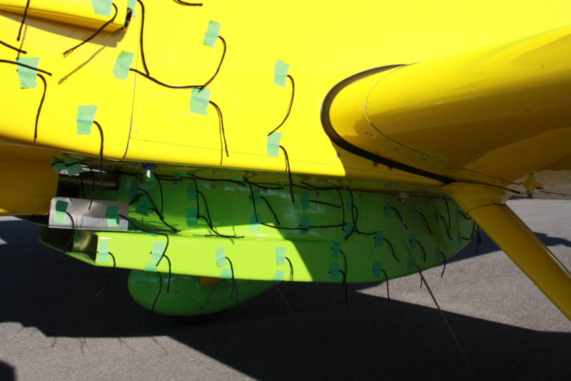
Wool tufts on scoop and fuselage
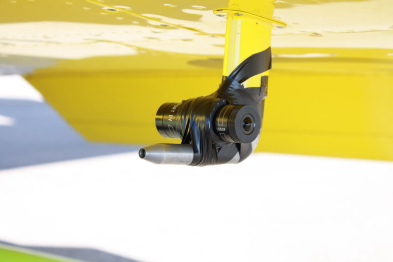
Vid cam mounted on pitot tube
Dec.2/13
Flying has been sidelined by trips, weather and the persistent radio problem for some time. I finally got up for 2 test flights last weekend with the intercom jury rigged to use the copilot's channel. This seems to work fine so it looks like finally I have isolated the radio problem to that. I've ordered a replacement intercom and hope to get that installed while the cold weather prevents further flying at the moment. The flights at -5C showed that the new cabin heat system is reasonably adequate for winter flying probably down to -15C or so. The thermostat was able to maintain a minimum of 58C in the decent with the rad door in the neutral position.
Feb. 26/14
I got flying again last week after many cold weather delays. So far, the new intercom setup seems to have solved the problem. Weather is cold and snowy again but I'll be back up testing again soon when it improves.
July 28/14
Putting in test hours and some cross country flights again. Recently added a 1/4 inch high wedge to the exit door to restrict airflow and try to increase velocity.
Running some more tests to verify the data.
Aug. 25/14
Flight testing of the rad setup is finally complete. By blocking off the cabin heat exchanger inlet, I was able to raise the coolant temp enough to finally see the exit velocity higher than the inlet. At 80 knots, with a temperature delta of 52C, I saw 104.4% at the exit. Exit temperature delta has the biggest effect on momentum recovery. The Meredith Effect theory is validated on my setup at least. I learned a lot and it's always fun to do the testing.
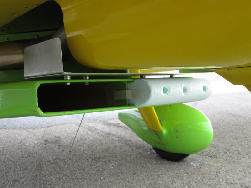
Sept. 13/14
Now that the colder weather is here, I am having trouble keeping the coolant temp up in a safe zone. I blocked off 1/3rd of the heater core which did almost nothing. I then decided to block off almost half the main radiator inlet. A vertical splitter divides the rad duct into left and right chambers so by blocking one side, effectively only half the rad core is now used. I drilled three, 1/2 inch holes in the foam plug to keep a little airflow past that side of the core. A test flight today at 1C OAT showed this finally brought the temps up in the climb and cruise to 70C/160F but still required that the exit door be closed. This goes to show the tremendous efficiency of the new rad setup. I'm only using about 15 square inches of inlet area to cool the engine at these temps.