

08/14/00 Wing Leveler Installation
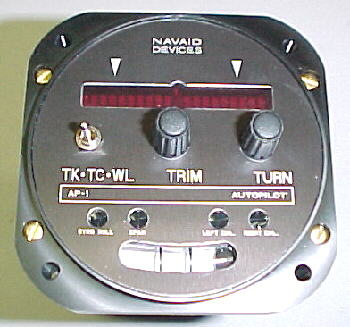
I'm installing the popular Navaid Devices AP-1/S-2 gyro/wing leveler. Navaid was quick in replying to my inquiry. Unfortunately they have a several month backlog on the panel mounted gyro component. I am on the waiting list for this part but they were able to send me the servo which I received in short order. They have an excellent website at www.navaid-devices.com for more info.
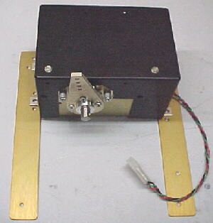
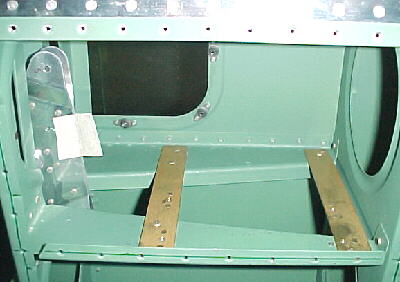
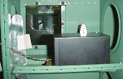
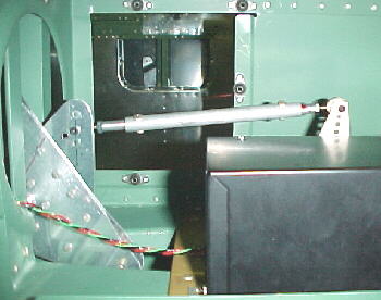
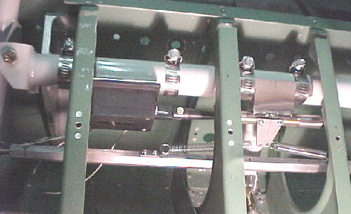
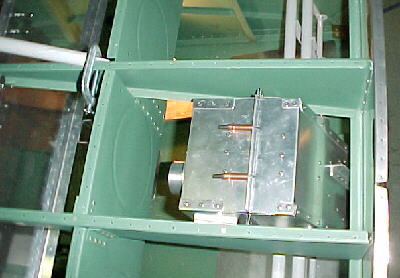
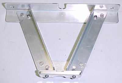
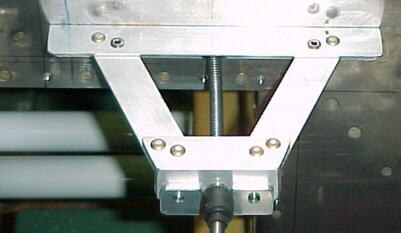
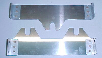
After looking at various ways and locations for mounting the servo, I decided on the right wing, above the access panel. I orientated the servo so that the cover could be easily be removed for adjustments. I did not mount the servo in the fuselage as others have done as this is difficult to avoid elevator movement with the RV control arrangement and involves much cutting of floor ribs. The mounting was accomplished by cutting 2 strips of .065 2024 about 7 inches long and 1 inch wide. These were riveted to the existing W-425 braces and put the servo at a nice height for attachment of the pushrod to the aileron bellcrank. 1000-08 nutplates were added to the mounting strips to allow easy installation and removal of the servo.I turned the crank 180 degrees to permit the proper motion.
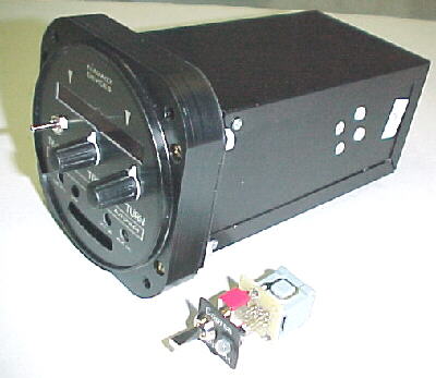
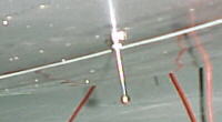
AP-1 gyro
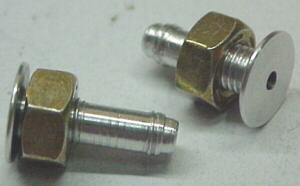
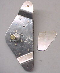
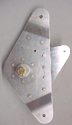
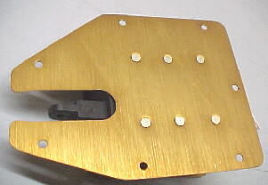
I fabbed a simple extension to add to the aileron bellcrank for the servo pushrod to drive. This was riveted to the bellcrank. Pushrod length has to be carefully determined to be sure that the servo does not bind over the full control movement. I had to drill another hole in the bellcrank arm to get the proper ratio and leverage here.
08/30/00 Elevator Trim Servo installation
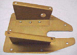
This was another case of a lack of updates by Van's. The kit contains many parts not required on the QB and the instructions are not updated to reflect these. Much of the work is done from the factory. You only have to cut and shape the Z brackets which hold the servo in place and rivet them on to the access cover which is precut. The instructions say to refer to drawing 3 or 3A. This in incorrect. Details are on 5PP. The factory also supplied flat head #6 screws to attach the plate to the elevator. These are obviously wrong as the cover and structure underneath cannot be dimpled or countersunk for these. Be sure to position the servo mounts carefully as access is tight. The instructions are poor with regards to dimensions.
Aileron Trim System 09/04/00
After looking at the drawing supplied with my electric aileron trim system and finding that they were for an RV8, I searched through the manual to try to find the correct drawing. I did not like the idea of cutting up the aileron and adding a pound of new structure and servo into one aileron. I have decided to mount the servo on the control column and design my own trim system.
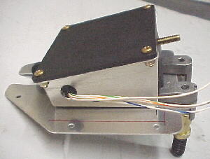
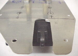
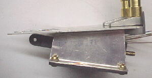
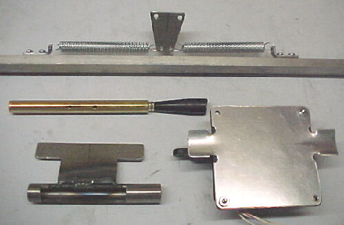
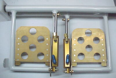
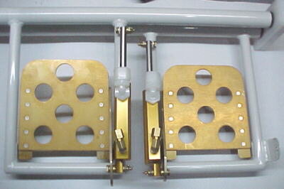
The MAC servo was mounted to the control column tube using a sheet aluminum bracket and hose clamps which are not elegant but very strong and light plus they allow adjustment of the assemblies. The standard MAC stainless threaded pushrod is shortened and is threaded into a machined brass bar which is tapped for two 4-40 machine screws, to mount a spring drive plate. The plate is made from .063 steel sheet. The brass bar slides inside a 4130 tube which has a milled slot to allow movement of the spring drive plate. The 4130 tube has a .063 steel mount welded to it which is clamped to the control column tube. Springs are attached to the hex link bar via two .063 steel mounts which use two 4-40 machine screws each. The whole assembly only weighs a few ounces excluding the servo. Pushrod movement from the servo tenses one spring and relieves tension on the other spring. This puts a force on the link bar to deflect the ailerons slightly. Certainly a more efficient and elegant way of trimming than deflecting an ugly piece of hinge material tacked to the trailing edge of the aileron plus it does not affect aileron balance from one to the other. It took about 10 hours to design and machine/fabricate the parts.
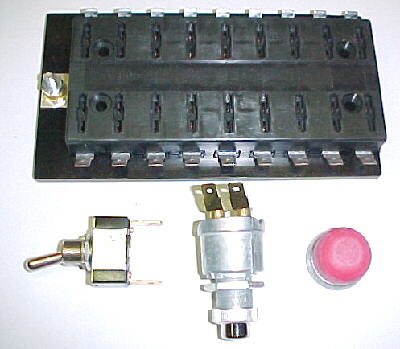
10/06/00 Electrical Parts
I decided to use Cole Hersee switches and fuse blocks as I have had good experience with these in racing cars. Toggle switches are PN 55014 with male spade terminals. The starter switch is PN 90036-02 with the red rubber cup PN 83280-02. The bus bar/fuse block is an 18 fuse model allowing for future growth, PN 46377-18. This block takes blade type fuses or automatic reset type circuit breakers and is very lightweight and logically designed. I plan to use the fuses as they are lighter and cheaper than standard aircraft type breakers.
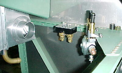
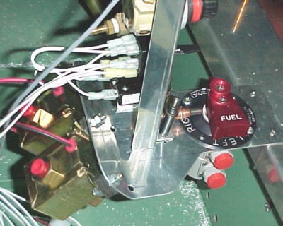
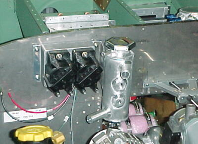
11/07/00 Console, Fuel Selector, Low Pressure Fuel Pump Mount
The fuel injected Subaru could not use the Van's supplied fuel selector valve due to its requirement for fuel return lines back to the selected tank. An Andair billet valve FS20-20-D2 will be fitted.
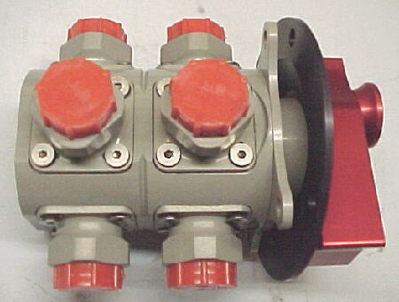
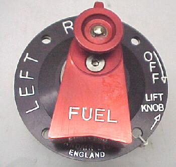
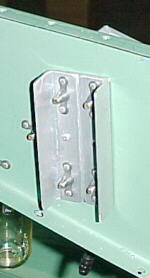
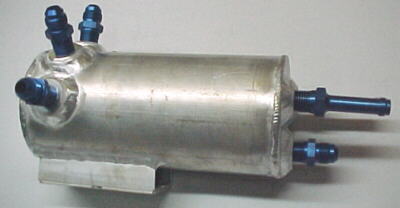
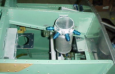
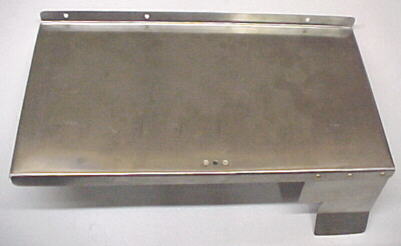
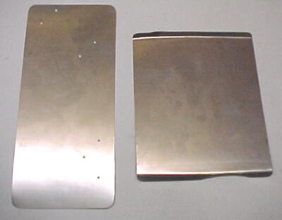
This change required a different mounting system for the valve. The factory setup seemed complicated with many pieces.I also wanted to mount the 2 low pressure Facet fuel pumps close to the selector for positive feed to the firewall mounted surge tank. I incorporated the console mount and the fuel selector/fuel pump mount together so that they are easily removeable with #8 screws. The Facet pumps are mounted underneath the .065 2024 plate on rubber/stud isolators as they are very noisy if mounted directly to metal.

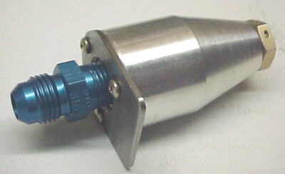
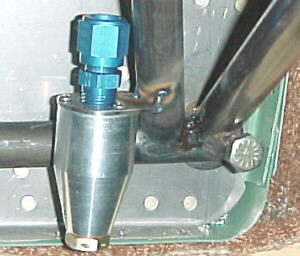
Facet low pressure pump
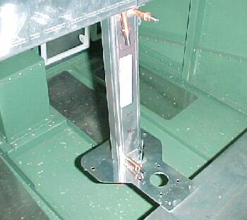
Console/valve/pump mount
The console will mount the following controls from top to bottom: Throttle, mixture control, wastegate controller, propeller switch and propeller circuit breaker.
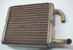
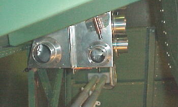
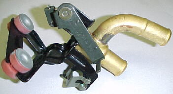
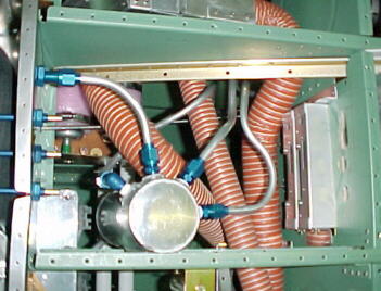
Heating/Ventilation System
With the water cooled engine, it made sense to use water for cabin heat. I selected a brass core from a Toyota Corona for reliability. I built a plenum box from .028 aluminum to hold the core and duct air through it. The box will be mounted between the middle and right upper fuselage stringers behind the firewall.
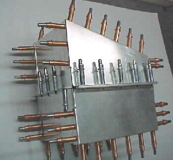
Air will be ducted from twin side mounted NACA ducts through 2 inch SCAT hose to the plenum box. All heating and ventilating air must flow through the core. A heater control valve regulates water flow through the core and air temperature. With the heater valve shut off, ambient air is available through all 5 vents. One 2 inch Whisperflow vent is mounted to defrost the windscreen, 2 are used to supply air to the foot/leg area and 2 smaller airline type eyeball vents are mounted on the lower, outboard panel edges for the body/face area connected to the plenum with 1.5 inch SCAT hose. All are individually adjustable.
11/12/00
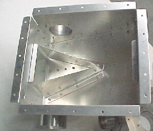
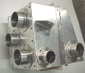
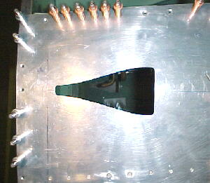
The box was riveted uses stainless pop rivets. A V shaped air diffuser is fitted between the two air inlets to turn and distribute the air more evenly over the heater core. The core lays on L shaped tabs and is sealed with foam inside the box. Two #8 screws and anchor nuts hold the box to the bottom of the fuselage stringers and one -3 bolt holds the front to a vertical angle piece of the firewall bracing. The assembly is easily removed from below in a few minutes.
11/13/00
I built mounts for two Wisperflow vents for the feet/leg area. These can be adjusted directly with the hands for direction and amount.

Two aluminum, airline style eyeball vents are panel mounted for the face. I had to fab hose adapters to connect these to the 1.5 inch SCAT hose. The plates are threaded for 8-32 screws. These vents are fairly expensive but beautifully designed and made. The Wisperflow vents are big and ugly and I just didn't want them within sight.
11/15/00
After careful consideration on placement of the two NACA ducts for ventilation air, I took the plunge and drilled some big holes in the side of the fuselage skin. The holes were trimmed out close to the line with snips, filed and sanded to shape.
11/20/00
I ordered a heater control valve from a 1984 Toyota Camry (OE PN 87240-32020) as these have proven to be extremely reliable. It will be mounted on the right side, between the firewall and second former.
11/23/00
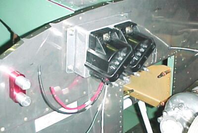
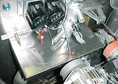
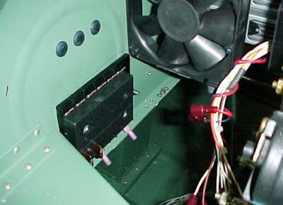
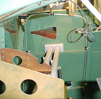
After much consideration with regards for leg clearance, wire routing and repair access, I built mounts for the Narco encoder, master solenoid, fuse panel, avionics cooling fan and SDS ECU. These are all mounted with screws and nutplates.
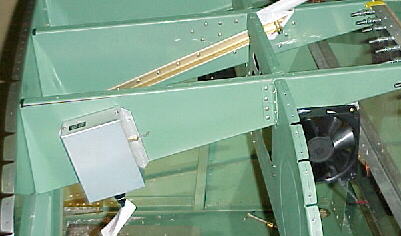
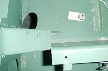
Narco altitude encoder and avionics cooling fan
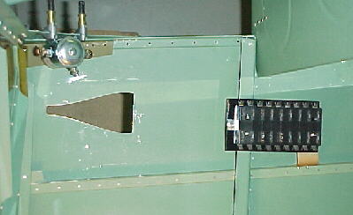
Master solenoid and fuse panel, right side
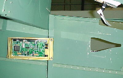
ECU, left side
11/26/00
I finally finished preparing the front top skin by drilling the holes to mount the defroster vent and the King GPS antenna.
11/29/00
I fabbed a bracket to hold the ammeter shunt in place
01/04/01
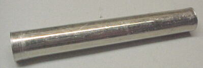
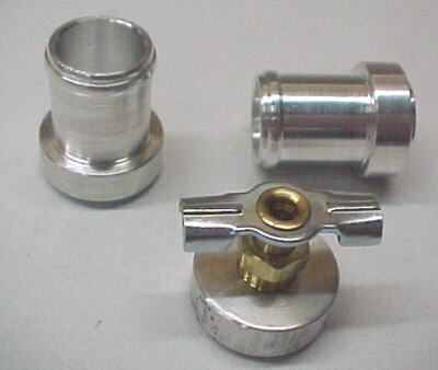
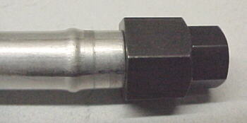
I machined two barbed coolant pipes for the heater system from 2024 bar stock to project through the firewall. These are held in place by two Earls anodized cable separators and isolated from firewall chafing my O-rings sandwiched between the separators. The heated hoses connect to the engine and heater core/control valves with 5/8 silicone heater hose and conventional clamps.
01/08/01
The SDS 4F ignition coil pack was mounted to the upper right firewall area via 2 clamping strips, four #8 screws and two 1/2 X 1/2 X .065 angle stiffeners rivetting to the back side of the firewall holding anchor nuts.
I fabricated a mount from 6061T6 angle to hold the throttle cable in position. This fastens to the firewall with two #8 screws and anchor nuts.
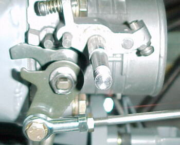
The springs, spacers and extra linkage levers were removed from the throttle body and a rod end with a -3 bolt ran right from the cable to the throttle shaft.
01/15/01
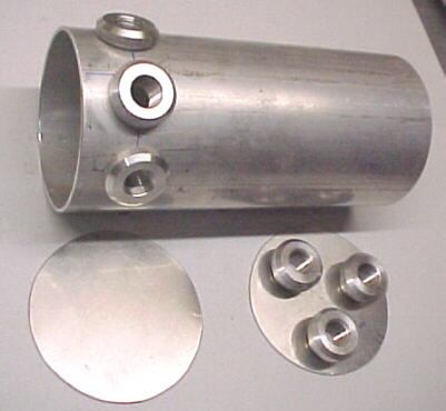
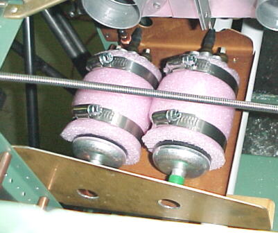
After agonizing for several hours about where to mount the fuel header tank, it was determined that it could not be mounted on the engine side of the firewall as originally planned due to interference with the intercooler and piping. The tank will be mounted on the cabin side of the firewall. The tank was fabbed from 3 inch diameter .065 6061T6 tubing and a bracket was fabbed to hold it securely to the left upper stringer on the opposite side from the Narco altitude encoder.
A bracket and tray were then fabbed from 2024 sheet and tied into the rudder bar support bracket coming off the firewall to mount the twin Bosch high pressure pumps which are gravity fed by the header tank. The pumps are wrapped in medium density foam for noise suppression
The twin, low pressure Facet pumps are mounted on the fuel selector console plate off rubber isolated studs. These feed the header tank from the wing tanks.
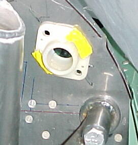
Canadian aircraft require a gascolator drain to check for water. In the case of an EFI installation, a 3/8 rigid line is run from the bottom of the header tank to a standard aircraft spring loaded quick drain fitting mounted on a resorvoir adapter block on the engine side of the firewall. This can be accessed through a small hole in the bottom of the cowling with a standard probe type fuel sampler. The adapter block was machined from 6061T6 billet.
01/21/01
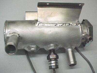
I fabbed the water header tank from 2.5 inch 6061T6 tubing. This has the inlet and outlet hose connections, rad cap, pressure and temperature sensor bosses welded on. It is mounted to the firewall as high as possible, beside the coil pack. Water inlet from the rads is directed at a tangent to the tank walls to swirl the flow for air removal. A Moroso 63485 weld-in filler neck was used.
01/24/01
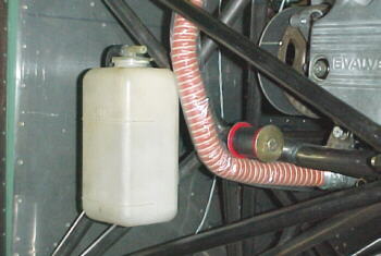
I built a bracket which was welded to the engine mount to hold the Toyota Corolla coolant overflow tank.
01/28/01
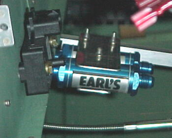
A bracket was formed from .065 2024T3 to hold the twin, Earls fuel filters mounted behind the panel. These are located between the low pressure pumps and fuel header tank.
02/25/01
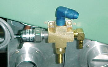
A brass fuel block mounts the pressure transducer, twin fuel inlets from the high pressure pumps and the outlet fitting which leads to the firewall fitting. This was mounted to the right upper stringer.
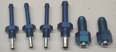
I machined several fittings for the fuel, vacuum and wastegate control systems as the fittings that I wanted were not made. I wanted flexible connections between the airframe and engine.
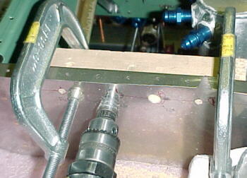
Drilling the holes in the thin stainless firewall material for the fittings is a chore as the material tends to get pushed in, leaving a raised edge. I found that clamping a piece of wood behind the firewall helped reduce this when using a unibit. Conventional drills over 1/4 inch would tend to rip the material. The 1 inch holes for the nylon wiring grommets were done with conventional hole saws. These worked very well when backed up with wood to support the stainless and provide a more substantial pilot.
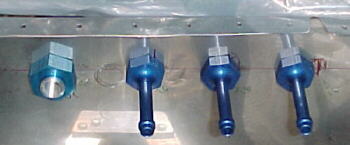
Most of the fittings were placed along the top of the firewall for easy access. Twin wiring grommets are placed on either side above the upper engine mount pickups to allow easy routing of the wiring. The fuel drain fitting and vacuum pump fittings are located on the right middle side of the firewall.
03/07/01
I built several heat shields to protect various components from the high infrared radiated by the turbocharger and exhaust system. I used .016 301 stainless for these.
Protects coolant hoses, fan belt, coil pack
Left shield protects coolant expansion tank, right belt and crank harmonic balancer
In position
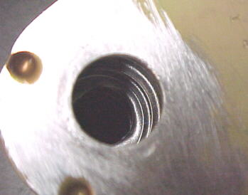
I sourced a couple of isolation bushings in the boneyard which I have used in various locations:
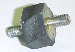
Isolated 6mm stud bushing from VW Fox firewall mounted solenoid
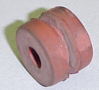
Heater valve bushings from '84 up Toyota Camry/ Celica
03/13/01
A GM evaporator core from a '92 Cavalier will be used for the left radiator. I cut off the aluminum freon lines. Then the holes were enlarged with a 3/4 unibit. It was found that there were internal baffles which needed to be drilled through on one tank. This was accomplished by drilling out the opposite end of the tank.
I started with a new core which I would highly recommend as the drill chips cannot easily be washed out of a used core. I machined fittings to adapt the 3/4 rad hoses to the core and another fitting to mount a petcock for purging air from the system on top of the core.
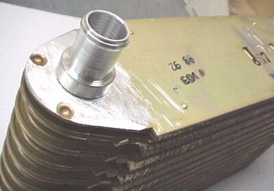
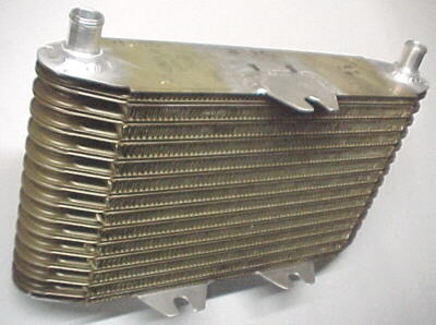
03/19/01
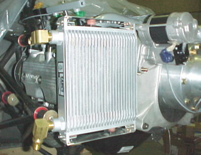
The right radiator is an Earls oil cooler. I fabbed a couple of mounts to hold the rubber isolator bushings as it has to be mounted to the engine and sub mount. Clearance is very tight and I will likely have to build some custom fittings to clear the cowling.
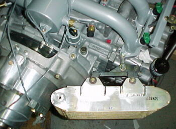
03/20/01
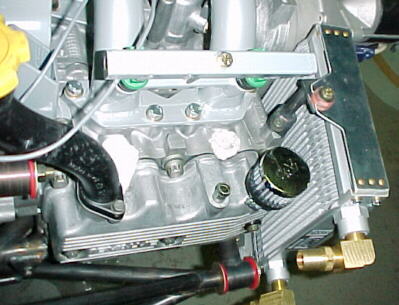
The right rad is mounted with 3 bushings. Threaded tabs are welded to the right lower engine mount cradle.
03/22/01
The left radiator has the fittings and mounting tabs welded on.
03/24/01
The left upper rad mount was fabricated and bolted to the left head and the lower mount was welded to the lower left mount cradle.

03/29/01
The rigid aluminum fuel lines were run into the header tank and to the firewall connections, Careful planning of the line layouts were required to provide room for routing of the cabin heat/ventilation hoses.
Earls tube beader makes beading easy for hose retention
04/01/01
After several hours of reading installation manuals and contemplation, I finally decided where to mount the two comm antennas and transponder antenna. The Rami transponder antenna had to be located at least 3 feet from the transponder to minimize RF interference and away from other projections. I wanted this to be accessable as well. It was mounted on the left side of the elevator pushrod tunnel. The lead will run through the spar wiring hole provided.
The two comm antennas were mounted underneath the main landing gear weldments as this is wasted space and allows easy access and cable routing. I chose Rami stainless whip types as these are low drag, easy to mount and trouble free at the expense of a slight loss is the high frequency ranges possibly. We'll see how they work in the air.
04/04/01
I spent several hours mapping out the electrical system and came to the conclusion that another fuse block had to be installed for the avionics. This block will get power from the main bus through the avionics master switch. I used a Cole Hersee 46377-12 block.
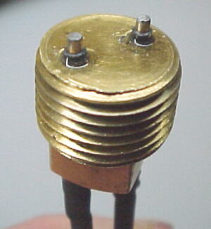
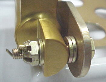
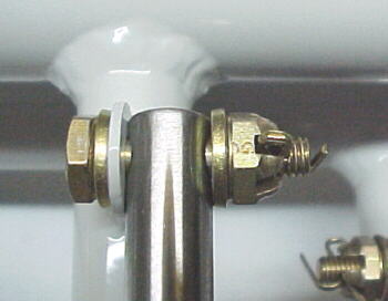
I fabbed a chip detector for the redrive using a brass pipe plug , two rare earth magnets and 2 steel electrodes. The magnets are mounted down the center of the plug with the electrodes on either side. When enough metal chips or fuzz build up between the electrodes, they complete the circuit and turn on a warning light on the panel. A temperature sensor will also monitor the oil temp in the redrive through the digital gauge system.
04/16/01
I have been stripping completed assemblies off the airframe to prepare to skin the upper forward fuselage. The panel is out for painting and the welded parts such as the engine mount will be sent to be powder coated. I have final assembled the rudder bars and brake assemblies.
Left side
Right side
04/19/01
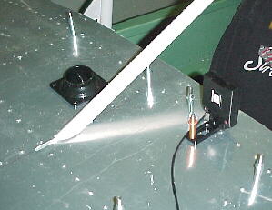
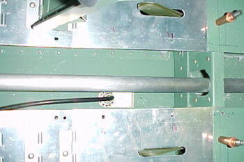
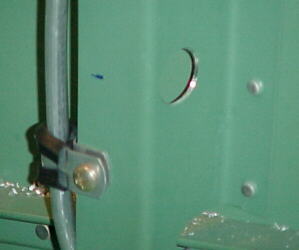
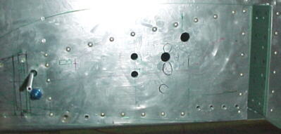
Now that I'm back to Van's plans and manual, the old familiar frustration sets in again. After over 3 hours of looking through the manual and plans, I finally decided how and where to run the brake and fuel vent lines. Drawing 49 has several depiction errors, no useful dimensions and the "scale drawings" are indeed not to scale so you can't measure from them. Here is how I located the holes. Refer to the photo below.
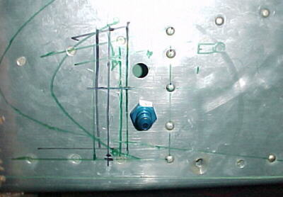
For the fuel vent line hole (upper), measure 14.188 from the forward spar opening which should be about .875 forward of the vertical centerline of line of rivets. Measure up 2.875 from the horizontal centerline of the line of rivets below. Pilot drill and enlarge to 7/16 with a unibit.
For the -4 brake fitting (lower), measure 14.065 from the forward spar opening and 1.5 inches up from the horizontal centerline of the rivets below. Pilot drill and enlarge to 7/16 with a unibit.
There is minimal room for error on these two holes due to the proximity of the forward wing attach bracket and the vertical angle structure on the inside which the lines must clear.
I also found that I had to bend the angle piece which hold the flexible high pressure brake hoses to the firewall. The lines had insufficient clearance to the angle firewall braces to be screwed on. Had Van's simply bent this piece to 95 degrees or made it a 1/4 inch longer, the holes could have been drilled more easily for the AN fittings and everything would have fit. Just a simple piece which was poorly designed.
04/23/01
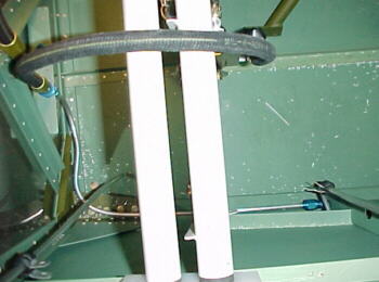
I decided to run the fuel vent lines and brake lines while the the front upper skin was off, figuring it would be WAY easier. Watch the proximity of the vent lines to the rudder cables. I also drilled all the rudder cable holes which were not done by the factory. They had dimensions for locating some of the holes but not all.
I used a piece of aluminum welding rod to bend patterns for the rigid aluminum tubing.
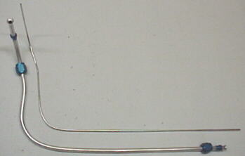
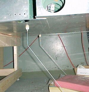
Left brake lines
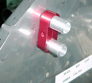
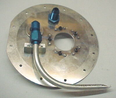
I drilled 9/16 holes in the fuel tank cover plates for -6AN fittings for fuel return from the EFI system. These will be sealed with Earls Stato-Seals instead of Proseal.
Holes were located and drilled in the fuselage for the fuel feed, return, pitot tube, fuel senders, nav light wires, pitot heat wires and wing leveler servo.
05/07/01
I machined the AN fuel vent fittings down to reduce drag and added the 45 degree angle.
05/08/01
I started fitting the fuel senders into the tanks. The left sender went well, bending the float arms as per figure 719. The manual contradicts itself with regards to the ohms readings. In one place it says 20 ohms for full tanks and in another it says 30. Mine read 30 and 249 at empty. The right diagram is wrong in Fig. 719. If you bend it this way, the float will be above the wing surface at full travel! It is also unclear if my senders were the correct ones. They have the correct PNs for left and right but seem to be the same. I had to re-bend the right arm and swap the float around to the other side to clear the stiffeners inside the tank. I checked for clearance and proper ohms readings by turning the tanks over on the bench. It took several tries before getting full readings in both directions without the floats hitting the skins.
05/21/01
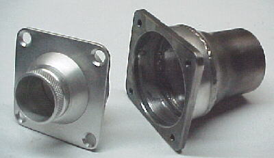
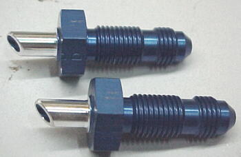
I didn't like the cheesy method Van's described for the static ports, using rivets and RTV so I machined up a couple of proper threaded ports out of 2024 T3 bar stock. I mounted these in the recommended locations. They will be connected with the polypropylene tubing provided and routed along the right side of the fuselage to the panel through grommets.