

Instrument Panel Mounting 09/11/00
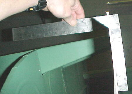
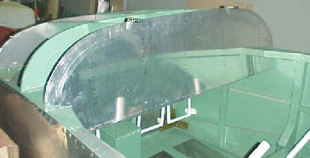
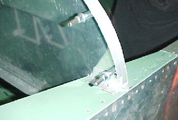
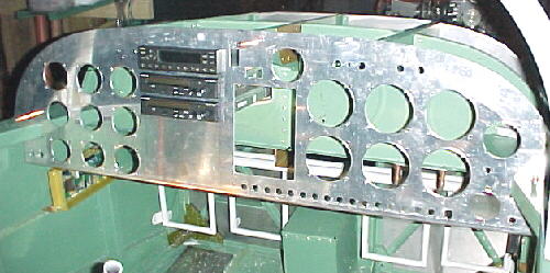
Here is yet another case of frustration with the plans. After carefully fitting the panel to the prescribed dimension in the drawings, I found yet another howling error. The panel did not have the correct angle with the upper front skin.
The plans specify that the lower base of the panel should be 23.0 inches from the firewall. As you can plainly see in the photo above, the perpendicular angle to the upper ribs does not match. These must be aligned for the 90 degree angle to attach the top skin. Again, by measuring the 1/4 scale drawing, SC-3, you get a dimension of 22.5 inches and the actual correct dimension is about 23.5 inches on my aircraft. This is only a 1 inch difference! It is really hard to believe that there are so many glaring errors on the plans after over 10 years on the market.
09/19/00
I decided to build a deeper panel than the one that Van's supplied to have more room for things. There is plenty of leg room to do this. I have also decided to fly the aircraft from the right seat so that I can have the stick in my right hand and throttle in my left. Purists may be shocked, but it is ergonomically better for a right handed pilot.
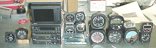
I unboxed all the instruments and avionics that I had acquired up to this point and started planning the panel layout while waiting for some more 2024 for the panel to arrive. I will not have the Navaid Devices autopilot gyro until February but its size is known.
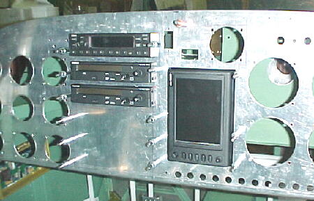
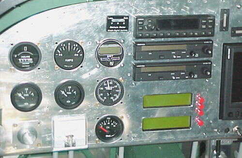
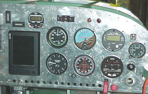
Here is a picture and list of instruments and avionics which will be fitted:
GPS- Bendix/King/Honeywell Skymap III Color
Transponder- Garmin 327GTX
Comm 1- King KY97A
Comm 2- King KY97A
Intercom- Hypervox HV-1
LCD instrument package- SDS, displays all ECU parameters including fuel flow plus temps and pressures
Trim indicators- Menzimer LED types
Altimeter- Taskem multifunction, includes OAT, ox and altitude alerts, rate of climb
Attitude indicator- Wultrad vacuum
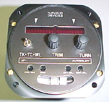
Turn & bank/Autopilot Gryo- Navaid Devices electric
VSI- UMA U-400
DG- Sigmatek vaccum
Magnetic compass- PAI-700
Chronometer/ clock- Astrotech
ASI- United to 220 knots
EGT- Electronics International 4 probe LCD
Manifold pressure- UMA to 50 inches plus LCD display
Hour meter- Datcom
G meter-
Ammeter- UMA
Oil Pressure- Mitchell
Propeller ammeter- Bach/Simpson
Switches and fuse panel- Cole Hersee
Oil pressure and redrive chip detector lights- Press to test MS25041 aircraft types
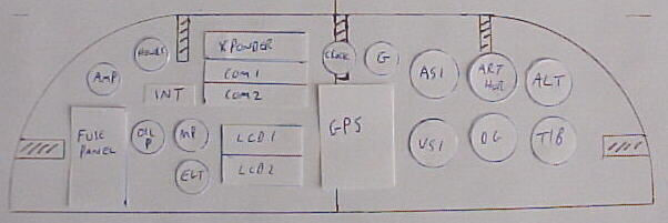
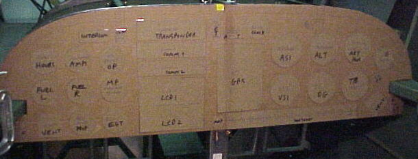
I did a preliminary layout on a 1/5 scale drawing with paper cutouts for the major pieces. Some juggling is required with the panel braces behind and the very deep King comms. Switches will be on the lower right. Here is the layout so far:
09/27/00
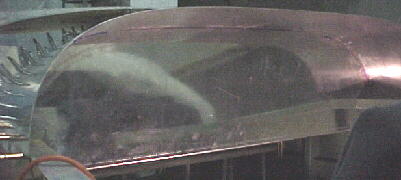
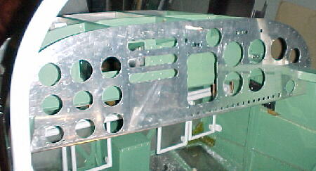
The new panel is 1 inch lower than the factory one for more space. It's shown here in its rough trimmed form.
10/15/00
I trimmed out a piece of .063 Lexan sheet to act as a template for the panel. I fitted it as close as possible to the inside of the skin and then traced the outline onto the rough cut panel. I cut outside the line and then spent about 4 hours fitting and filing until the panel fit just right. This is tedious and time consuming but is the only way to get the proper fit.
10/18/00
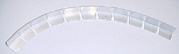
I cut 4 pieces of 6061T6 3/4 X 3/4 X .063 angle for the upper mounting flange of the panel. These were relief cut to allow bending to the panel contour. The parts were then drilled and clecoed.

10/20/00
Two pieces of .065 X 3/4 6061 angle were cut to mount the lower enge of the panel to the canopy sills. I found that Van's had not been too accurate in riveting the second former in place and it was 3/16 different from left to right as measured from the firewall. This is not a good place to measure from. I measured from the firewall back and from the seatback capture angle forward to be sure that the panel was square in the fuselage. Also remember that the dimension on the plans is incorrect as far as the lower edge of the panel mounting goes. This needs to be moved back about 1/2 inch to establish the correct angle on the panel to match the top skin taper. I have decided to rivet the main panel piece in as removal once the skin is riveted in, looks to be nearly impossible. One #8 screw will go through the top middle stringer and one through each piece of angle on the canopy sills as well.

With the panel clecoed in 3 places, I marked the underside of the top skin where the top panel angle pieces were, removed the skin and marked the rivet spacing on the bottom. These holes were then drilled on top of particle board. The skin was placed back on the fuselage and the holes were drilled through the panel angle underneath.
11/13/00
After over 15 hours of trying and planning, I have a final panel layout now for all the main components. I found that several items had to be relocated. The upper gyros in particular would not clear the support bracing behind and had to lowered. With everything accounted for, there was no room on the panel for any more gauges, maybe a couple of warning lights. My cardboard layout does not show up well in the photos. I'll try to post a better picture when everything is tranferred to the lexan cutout.
11/26/00
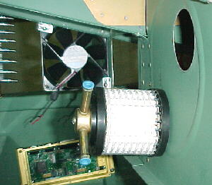
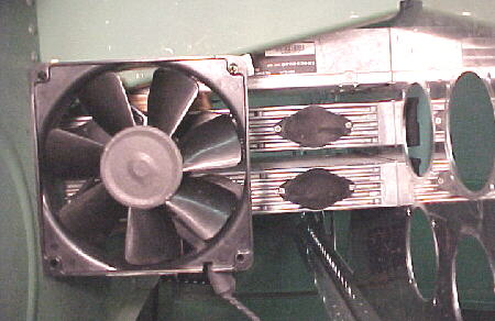
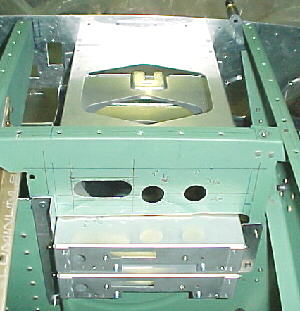
I had to move a couple more items to clear the avionics cooling fan. The intercom and comm select switch are now on the right side above the ASI and altimeter which is probably a better layout anyway. The mixture meter has been moved into the spot where the intercom was. The gyro air filter is mounted on the second bulkhead to the left of the defroster duct hole. Note avionics cooling fan and SDS ECU in the background.
12/03/00
Preliminary work on panel cutouts has begun. Several hours were spent marking hole centerlines.
12/05/00
Panel holes almost done. Added autopilot gyro hole, headphone jack, and warning light holes. Trial fitting radios.
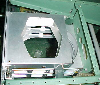
Cooling fan blows directly on comm heat sinks and transponder
12/08/00
I'm adding vetical stiffeners to the panel between instrument cutouts. Two of these serve as the front radio rack mounts.
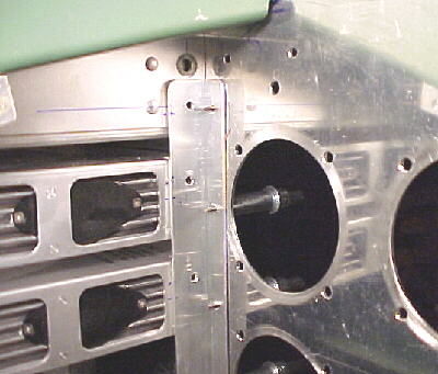
The twin King KY97A comms project through the second bulkhead and are supported by angle brackets. The shorter Garmin 327GTX transponder is mounted above the comms.
12/09/00
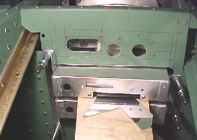
The Skymap IIIC GPS is a little tricky to mount. I bought the so-called panel mount kit which did make things easier. The GPS clips to this using a ball a spring clip arrangement. The GPS needs to be easily removeable to change data cards from time to time. I built a U shaped mount from .032 2024 T3 which ties into some vertical angle against the panel face.

12/20/00
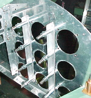
After much fussing, I finally got all the radio rack mounts finished. These demand precise fitting for the radios to slide in and engage properly. It is a very slick arrangement for quick installation and removal once the racks are mounted properly in relation to the panel. I've added 1/2 X 1/2 vertical angle stiffeners between instrument rows as well.

12/27/00
I drilled the center console for the engine and prop controls. From top to bottom: throttle, mixture, wastegate, prop pitch, prop breaker and fuel selector.
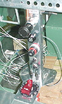
12/29/00
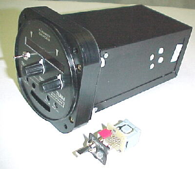
I received the Navaid Devices AP-1 wing leveler gyro today. This was fitted with the Porcine Smart Coupler and switch gear to translate GPS signals for heading tracking. The whole unit weighs only 1 pound and fits into a standard 3.125 instrument hole. Depth is about 7 inches. The display includes command knobs, turn LEDs and bank bubble. Very cool, light and inexpensive.
12/31/00
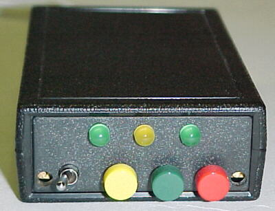
We designed a custom instrument array using two large, backlit LCDs and a microprocessor. This is programmable for alarm limits and monitors all normal sensor parameters from the SDS ECU plus 13 other parameters for the engine, redrive, coolers and instruments for R&D purposes. The system can be set to scan or locked in a particular window. It displays 4 parameters in each LCD and when limits are crossed, that parameter is flashed and a high intensity LED is illuminated. This saves considerable weight and panel space (of which there is none now) and allows the pilot to concentrate on flying the aircraft rather than scanning dozens of steam gauges.

01/02/01
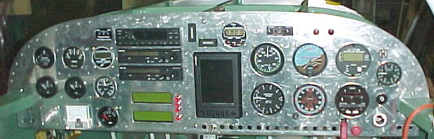
The full panel layout is finally done. It did turn out that there was space for the attitude indicator in the center just barely. I am very happy with the ergonomics and everything is readable and reachable. Now comes the wiring.
01/28/01
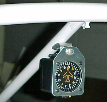
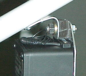
I built two brackets from .065 2024T3 to mount the PAI vertical card compass off the roll bar brace. A VW rubber shock mount isolates the unit from vibration. Two stainless 4-40 screws are threaded into the brace to retain the forward mount.
05/12/01
The panel was painted with Endura non-reflective grey and looks great.

06/12/01
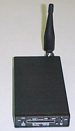
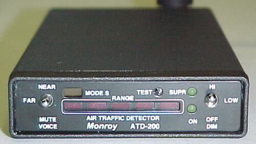
I'm adding two more black boxes to the aircraft. One is the Monroy ATD-200 air traffic detector. This small box detects transponder signals from other aircraft and displays both LED visual and aural warnings for range. I've decided that this may be better than strobes in my anticipated flying environment. "The Aircraft Consumer" tested and recommended this device. I ordered it online and had it within 48 hours. It appears well made and easy to hook up and operate. Price was $789.00US. It measures 5 X 2.75 X .75 and weighs about 10 ounces. I'll be mounting mine up on the right glareshield.www.monroyaero.com/index.html
The second box is an EZ-Trim altitude hold box which is tied into the electric elevator trim servo. It contains a microprocessor and pressure transducer. This combined with the Navaid Devices wing leveler gives 2 axis autopilot control for a very reasonable price.