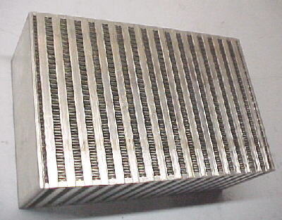
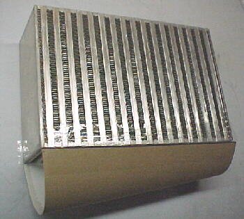
Ambient air flows through this surface


This article details the fabrication of a complete intercooler assembly using commercially available cores. Intercoolers are heat exchangers placed between the turbocharger compressor and engine intake manifold to drop the temperature of the compressed air and increase its density. The higher the charge density, the higher the power will be at a given boost pressure. The higher the boost pressure the more you need an intercooler.
Core Selection
We recommend using Spearco cores. They use a highly efficient pierced fin design on both the inside and outside of the tubes. This design offers high charge cooling efficiency and low pressure drop. Spearco offers a very wide range of cores and has an excellent catalog with detailed data comparing airflow rates vs. efficiency at various forward speeds. In dealing with Spearco for over 15 years, we have always had excellent service and their pricing is fair for the performance that their cores offer. If you are tempted to use OE intercoolers for a serious performance project, expect to be disappointed. Most OE cores are inefficient and have high pressure drops. You get what you pay for in this business.
Their website is at: www.spearcointercoolers.com
Ambient air flows through this surface
If you can afford it and you want maximum performance, always try to fit the largest core possible. Remember to allow for the size of the tanks and the piping required to hook up to your turbo and throttle body. Tanks will add roughly 4.5 to 5 inches to the size of the core in the dimension that the air flows through the tubes. The higher the number of tubes, the lower the flow restriction will be. The longer the tubes, the lower the charge temperature will be. As a rough rule of thumb for matching cores when the peak hp is known, figure 1.5 X HP = airflow in CFM. A 300 hp engine would be flowing about 450 CFM. For street applications, its nice to see pressure drops of less than 1.5 psi at peak flow and efficiencies of at least 75% at 50 mph. For race applications pressure drops should be under .75 psi and efficiencies should be over 90%. Generally speaking, increased core volume (height X length X depth) will give lower charge temperatures and lower pressure drops. Many people worry about getting lag with a intercooler setup. This is usually not a factor on a well designed system. Remember that our 300 hp engine was flowing 450 CFM or 7.5 cubic feet /second. Even with a huge core having a tube volume of .5 cubic feet, the core would be completely aspirated in less than 1/10 of a second at peak rpm/full power.

Compressed turbo air flows through this surface
Low speed applications require larger surface areas to be effective while high speed applications can use lower surface areas. Ducting can substantially increase airflow rates through the cores and is often overlooked. Just because the airflow it hitting the front of the core, does not mean that there is much air flowing through it. Airflow is dependent on the pressure differential between the front and the rear of the core. Air exiting the core should ideally dump into a low pressure zone and the core face should be in a clean, high pressure zone.
Piping Choices
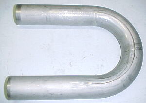
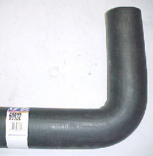
Most installations are plumbed with thin wall mandrel bent steel tubing. This tubing is available at race fab shops in various radii and diameters, generally in U or J configurations, which can be sectioned to fit together into the desired shape. It is relatively inexpensive and can be TIG or gas welded. Aluminum tubing can also be used but is harder to find and more expensive. Piping diameters are dependent mainly on engine airflow which is a function of HP. For engines up to 350hp, 2.25 inch tubing works well. 350 to 500 hp installations should use 2.5 inch. Engines above 500hp should use 2.75 or 3 inch tubing. Some means to take up vibration and engine movement to chassis mounted intercoolers is required. This usualy means flexible couplings. Moulded radiator hoses are available in larger diameters and various shapes and are generally safe at the temperatures and pressures required for street applications. You may have to cut or enlarge holes in your sheet metal for the piping to run to the intercooler. Watch hood clearnce and ground clearance to the pipes if they run over or under the radiator. Silicone hump hoses are also available to take up movement.
Tank Design
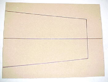
An effective tank design will spread the airflow out over the core tubes evenly and with a minimum of turbulence. You don't want a square tank with the inlet pointing straignt at the tubes 2 inches away. Most good designs use a converging tank when airflow is perpendicular to the core tubes. This is the design shown in this article. When the air inlet is parallel to the core tubes, a diverging design should be used. The air inlet and exit snouts will be the same diameter as the piping that you have chosen for your installation. This will decide certain aspects of your tank design.
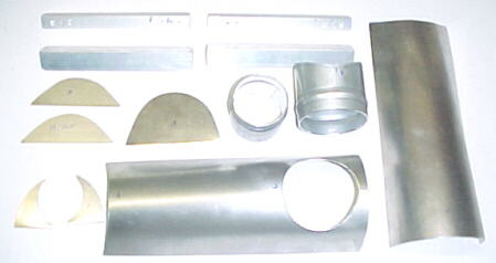
Measure up the core and decide where your inlet and exit snouts need to face and how the piping will run between the turbo and throttle body. Avoid running any more bends than required in your plan. Once the snout positions are planned, you can lay out the tank design on light cardboard and try the fit on the core. This tank design tapers in cross section as the air flows through. Make sure that your snouts have enough height to fit inside the tanks.
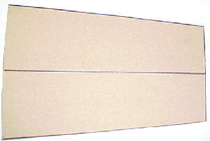
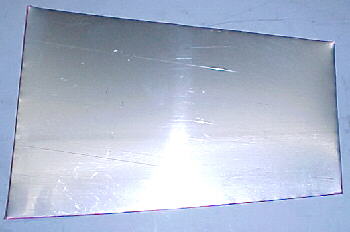
Once you are satisfied that the tank template is the correct shape, trace the outline onto your aluminum sheet. We use industrial grade aluminum with about a .050 thickness.
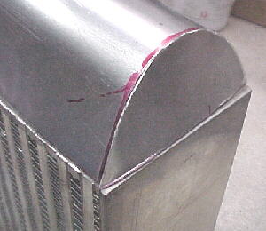
Forming the Tanks
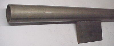
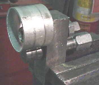
We use a piece of 2.25 or 2.5 inch steel muffler tubing with a short piece of plate welded to the center of it to hand form the main tank contour over.
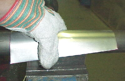
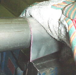
Trial fit the tank on the core and keep tweeking it until your get a close fit everywhere.
Snouts
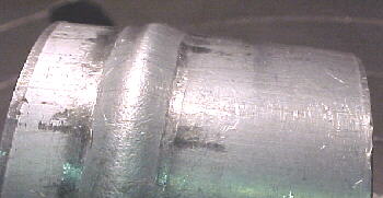
The inlet and outlet snouts are usually made from 6061 T6 tubing with a .049 to .063 wall. These should be cut long enough to allow for forming a hose retention bead, a hose clamp and the weld fillet to the tank.
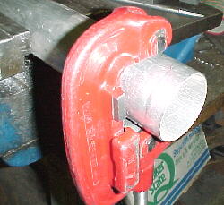
File and smooth the edges and roll a bead onto the snouts. The beads are VERY important if you don't want your hoses popping off all the time, especially if you use silicone hose which is very slippery.
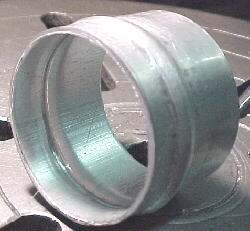
Check the fit of the snout in the tank.
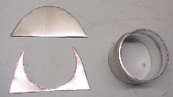
End Caps
The end caps to seal the tanks should be sloped to guide the airflow down the final couple tube sets. They need to tightly fit the tank and the core. These are made from the same material as the tanks.
You also need to cut a fill in piece to fit around the snouts and the front part of the tanks. Trace out the inside of the tank contour onto your aluminum sheet. Place the snout over the tracing where it will fit into the tank and trace. Cut on the lines and file to shape.
Mounts
It may be best to weld the mounting tabs onto the core side plates after the other parts are welded together and you can trial fit in the car. Mounts are usually made from .125 6061 T6 plate or strip stock. These should be welded to the thick core ends if possible or to the tanks in a pinch. The longer the tabs, the stronger the weld.

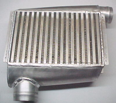
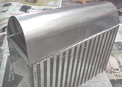
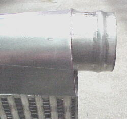
Finished intercooler assembly
Welding
The parts need to be TIG welded together by someone who has the right experience and equipment. Make sure that your parts fit well and tightly together as gaps make welding the thick to the thin difficult.
We will update this article as we get more photos of completed intercoolers and installations