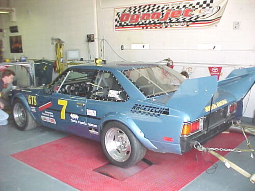


This article outlines some observations made during a tuning session on a turbocharged 20R Toyota Celica.
The engine on this car was a 2400cc version with 7.5 to 1 Mahle pistons, Crane 284 degree camshaft, Crower rods, Garrett TO4 with H3 compressor and O .69 turbine. Custom built header, intake manifold, wastegate and massive Spearco intercooler core are also fitted. An SDS EM-4 4F controls fuel and spark. MSD 72 lb./hr. injectors are used with 100LL avgas.
This engine had been tuned many years ago on an inertial engine dyno. Subsequent changes were made and tuning was carried out on the road racing track. On the DynoJet, we started out with boost turned down to about 3 psi, attempting to get a clean, baseline pull. The engine ran reasonably clean but the wideband sensor indicated the engine was way too lean. Fuel was added and the engine ran worse. The wide band showed lean still and the operator insisted it was correct. More fuel was added, the engine ran worse and lost more power. This made no sense and we concluded at this point that the meter was giving false information. The mixture was leaned substantially and power started to pick up on each run with the engine sounding better each time.
There is a lession to be learned here. The purpose of a dyno is to allow tuning to extract maximum torque at each rpm. It will do this without a wide band meter or EGTs or anything else for that matter. We wasted time believing the meter, doing 4 useless runs. The water trap for the sensor was eventually found to be full. With this emptied, the meter gave correct information. It did not make sense that if the engine was actually lean, that it would lose power and sound worse if we made it richer. The engine was actually too rich and we were making it worse. The engine will tell you what mixture it likes by making max torque when you get it right. The AFR is just a secondary number.
With this solved, we simply did pulls with the mixture knob at +5%, +10% and -5%. We looked at where it lost power and where it gained. We then adjusted the bad points with the programmer. Once we had things running clean, we started upping the boost pressure gradually, tuning to achieve max torque at each rpm. As we turned the boost up, we found that the curve had quite a bit of scatter or variation. This was determined to be caused by pressure spikes in the MAP sensor hose. The hose was orificed down and we saw a dramatic reduction in scatter. The variations caused the ECU to chase the MAP sensor input by adding or subtracting fuel. The difference between before and after adding the orifice can be seen below, run 8 is without orifice, run 9 with orifice.
We eventually retarded the timing from 32 degrees total to 28 gaining about 22 extra hp at 14 psi. The 20R has a high swirl combustion chamber, requiring less ignition advance than many other large bore engines. We also tested our 4F coil pack output by gapping a set of plugs at .050 inch. The coil pack had no problem firing these plugs at full boost and rpm.
This run shows observed hp at 14 psi
This run shows SAE corrected hp which is invalid for turbocharged engines
Many DynoJet operators plot SAE corrected HP for turbocharged engines. The standard SAE correction factors do not apply to turbocharged engines so this generally inflates quoted DynoJet figures. The higher the elevation, lower the barometric pressure and higher the temperature, the more these will be off. SAE hp is useful for comparing atmo engines only.
In conclusion, the tuning session was interesting and we found some power by leaning the fuel values slightly and retarding the timing also. The 20R has a relatively poor cylinder head and a lot of mechanical friction so the power numbers are not impressive. Torque is fairly good, but considering the truck roots of this engine, this is not surprising.