
Oct. 2016. We've sold our RV10 project. With the change in business activity and life, I just did not have time to complete the project or a need for a 4 place aircraft any more. Hopefully the new buyer will enjoy finishing it and flying it.
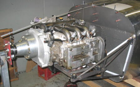
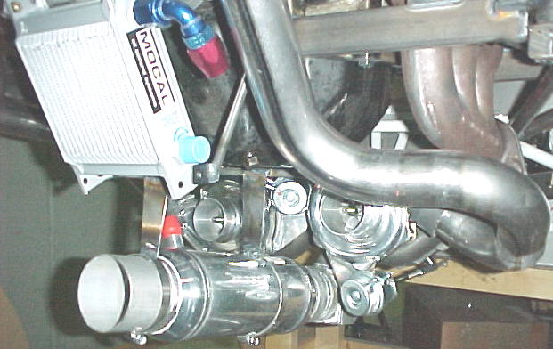
05/25/05 This page will detail the progress and mods to our RV10 project but won't go into the extreme detail our earlier RV6A pages did as there are many other RV10 construction sites already. Plans are to power the 10 with a twin turbo, Subaru EG33, six cylinder DOHC engine rated at 275 hp for takeoff. The reduction drive will be another Marcotte M-300 driving a 3 blade MT constant speed prop. Cooling will be via a P51 style belly scoop mounted rad with adjustable exit door. At this time, we have the engine, redrive and tail kit. The stab is done and work on the fin is progressing. We have fabbed a custom intake manifold and alternator mount detailed here: Subaru EG33 Intake Manifold
05/31/05
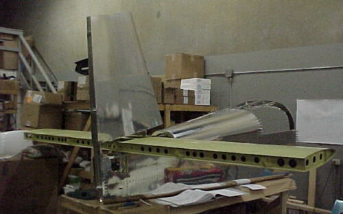
The stab and fin have been completed. I must comment on how nice this kit is the build compared to the RV6A QB. The pre-punched parts fit perfectly so far and only 18 hours were spent building the fin. It is relaxing rather than frustrating to work on the -10. Thanks to Van's for engineering such a fine kit and excellent manuals. Truly a quantum leap forward in just 5 years. On to the rudder!06/16/05
The rudder is now almost completed. The rest of the QB kit is in transit and set to arrive early next week. I'll post some photos then. I hope to make the RV10 cool properly the first time out with lower drag and weight than the setup on the RV6A.
06/23/05
Christmas in June. The rest of our RV-10 QB kit arrived on the 21st in 4 big crates so my spare time is all spoken for now. Van's used about 2000 feet of newsprint to pack everything well. It takes a couple of hours to fold all this up but at least it is packed well. Rudder is done and about half the work on the elevators is done.
06/27/05
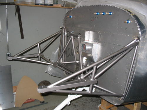
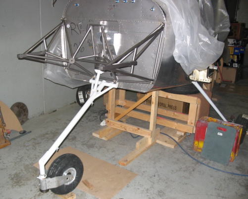
Photos:
07/11/05
Elevators are almost done now. Engine mount bolted up and I'm taking some preliminary measurements now on the Subaru EG33 interface, where the turbos, pumps and hoses will be routed and planning the engine mount configuration.

07/15/05
A few observations working on the elevators: There is no way I could find to set the solid rivets called for at the inboard rib/ rear spar, gusset junction, just no room to get in there. I substituted blind rivets here inserted from inside. Also not too impressed with the counterbalance tip ribs supplied by Van's. These were all warped and even after a couple of hours of massaging with fluting pliers, seamers etc. these still did not look great. Once riveted in place, the flanges were angled upwards slightly which may make fitting the tip fairings more difficult. The manual calls for some -4 rivets on the trim tab horn but tells you to dimple for -3??? Later instructions say to pre-drill two holes in the trim tab hinges then contradicts itself by saying later to line up and drill the aft one later???
07/21/05
The tail sufaces are all complete and work has begun on the tail cone. I had to return a Falcon Gauge altimeter to Van's that was out 400 feet when I got it! Sourced some lightweight Walbro fuel pumps to replace the originally planned Bosch ones. We now offer these.
07/25/05
Work is progressing on the tail cone.
08/01/05
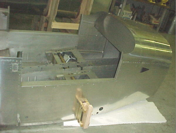
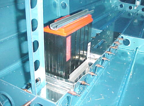
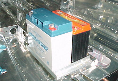
Ran out of clecos on the fuselage, waiting for more. I skipped forward some steps and worked on the battery tray. This had to be modified to take a lightweight PC680 battery with 3/4 angle brackets. The rest stays stock. Saves about 10 lbs. over the normal type battery which will come in handy for adding other things like a backup battery, autopilot servos etc. Spent many other hours recently planning out component locations and mounting for the engine mounts, turbochargers, intercoolers, ductwork, fuel system, cabin heating, radiators, oxygen bottle, belly scoop mounting, turbo scavenge pump, fire suppression system etc. As I delved through the plans and looked at how the RV10 goes together, I marvel at how well thought out this aircraft is and how complete Van's makes this kit. When you start to plan how you will make extensive mods to system like I will be, you really learn to appreciate how much thought and engineering has been done on the RV10. This is such a good value for the price of the kit.
Looks like the stock engine mount upper forward tubes will have to be cut off and the engine moved aft about 2 inches to suit the MT prop and spinner and allow the starter to clear the cowling with the least possible modification. Preliminary measurements indicate plenty of clearance for the intake manifold and injectors which I was worried about as this stuff was all built long ago. I have started researching parts for various system and ordering some of them to keep construction flowing. Holding off a bit on the avionics for now as this field changes so quickly but leaning towards an analog panel with Skymap IIIC GPS, Trutrak Digiflight autopilot so far.
08/03/05
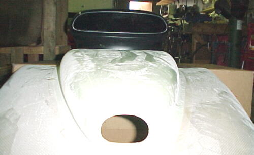
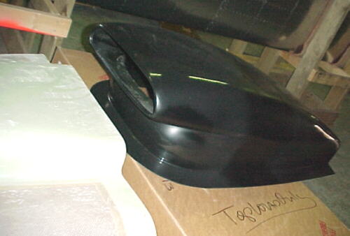
Received the radiator scoop which looks pretty good as a starting point. It will need some mods to the fore and aft ends to suit the installation but overall will save many hours of work.
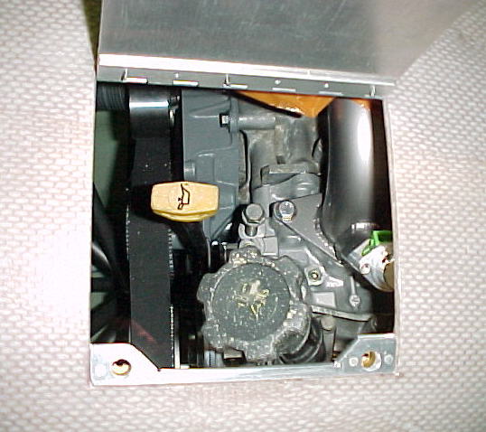
08/04/05
Had to find a suitable place to return the turbocharger scavenge oil so I removed the left cam cover. The cams were mint and the whole engine was spotlessly clean inside. Hopefully this bodes well for the condition of the rest of the engine. There are two convenient plugs in the front of each head, leading into the cam boxes with nice, large oil drainback passages. These will make ideal returns for the turbo oil.

09/10/05
Over the last month, I have spent many hours looking at the radiator placement problem. After studying everything from wing rooted mounted rads to surface conduction to rear fuselage mounted ones to cowling mounted ones, both horizontally and vertically mounted, I found none of these suitable for the purpose. I went back to the original belly scoop and suddenly had a new idea. I experimented with twin centrifugal blowers pumping through the cowling to simulate airflow and found that by placing a horizontal splitter between the bottom of the stock exit duct and the inlet of the rad scoop, the airflow could be controlled properly. This will mount the main rad and I'll have a supplementary heat exchanger mounted forward of the firewall which will act both as a rad and the cabin heater core. It will be fed by ram air with a selection door to dump air overboard for engine cooling or into the cabin ducts.
Work continues on the fuselage with most of the aft tailcone section now having beeen riveted together. Waiting for a few special tools to do more work on the aft section. Also found another error in the manual which calls for AN3-5A bolts in the battery tray area. These should be -3A.
09/26/05
Another mistake in the parts was found on the elevator bellcrank. It turns out that this was not formed correctly and the blades are too narrow to accept the rod end. These have to be widened .125. We have now fitted the stab to the tail cone. Coming along slowly.
10/26/05
Have completed the tailcone section manual and working now on the main fuselage section. Front floor board drilled and dimpled. Main landing gear mounts did not fit well and will require massaging and probably reaming just like the RV6A. Not too impressed with the hole alignment to the spars. I am fabbing the backup battery mount and working out details on the belly scoop, radiator and cowl flap actuation. Other details such as antenna placement, fire bottle location, fuel selector mounting, pump mounting and radiator piping have also been investigated.
10/28/05
Just added some more structure to mount the backup battery needed for the Sube.
11/03/05
Came across an error made by the factory on the left upper longeron. This was made too long. I had to de-rivet and carefully saw about 3/16 off and rivet together again. This would prevent the aft portion from going forward enough.
The front and back fuselage halves are now clecoed together. It has passed the canoe stage now!
11/20/05
The fuselage halves are riveted together and baggage door completed. One thing to note here- don't rivet the hinge to the door until last as this makes setting the front row of rivets very difficult. The hinge ones can easily be squeezed later. Work is stalled somewhat on the fuselage now due to delays with radiator vendors. This prevents me putting in the fasteners to the belly skin to attach the radiator scoop. Contemplating wiring in the fuselage as well before the floors are riveted on.
11/29/05
Finally decided on how many wires to run under the floorboards for the elevator trim, battery, master and autopilot trim servo. Got this installed along with soundproofing and have the rear floorboards riveted in place. Coming along much more rapidly now again.
12/13/05
Rear floorpans are in now. Baggage door done and mounted. Rear seats done. Building various small assemblies like elevator pushrods to have them ready for installation later. Waiting for the radiator which is holding up further work on the fuselage floor where it will be mounted to. About to start planning the panel layout.
01/13/06
I have been working on mods to the RV6A for the last couple weeks. Just received the custom radiator for the RV10 and completed some flow bench testing on it. I'm very pleased with the results. The core has about 1/4 the pressure drop of the commonly used GM evaporator cores so should offer much lower drag. Weight is about 8 lbs. Looks like money well spent.
02/03/06
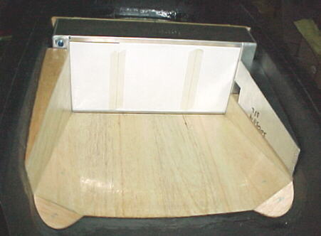
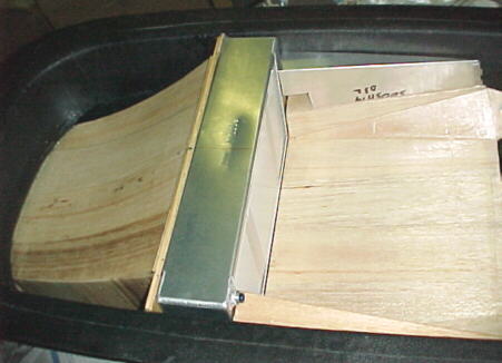
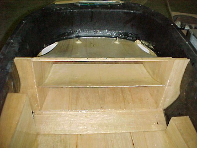
I've been glassing in the radiator mounts to the belly scoop. Balsa was used to form most of the parts with glass and epoxy laid over it. Lots of work.
02/24/06
Have added a pointed nose to the scoop to allow the cowling exit air to pass by more easily.
An aluminum horizontal splitter will keep cowling exit air from entering the radiator inlet.
04/10/06
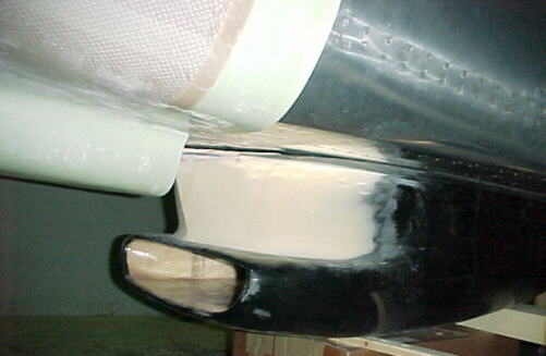
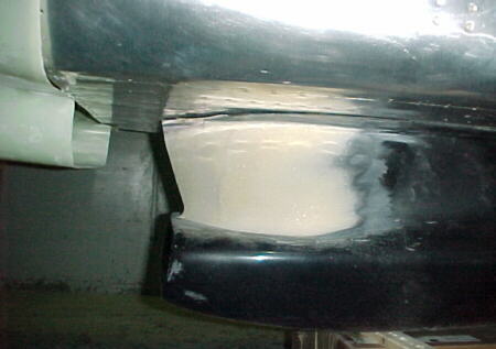
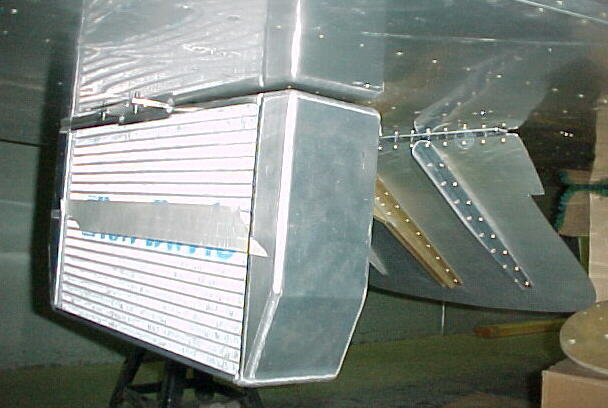
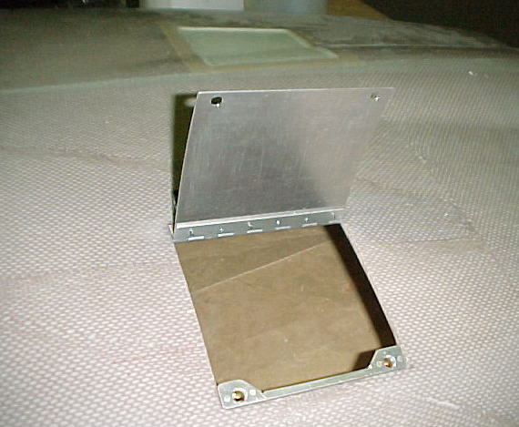
The scoop and most attachments and other parts are now finished.
Front view of rad scoop exit door
Rear view of door
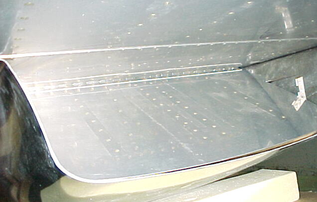
Closed door with scoop in place
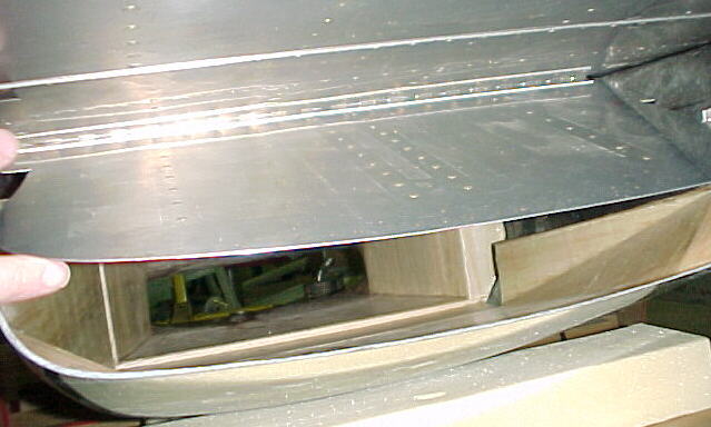
Door in half open position
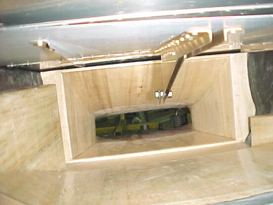
Door in fully open position. Note smooth contours of duct. Right side fairing not in place. Rad sits in middle recess.
06/13/06
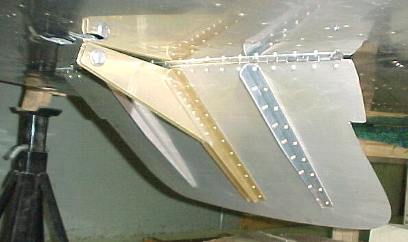
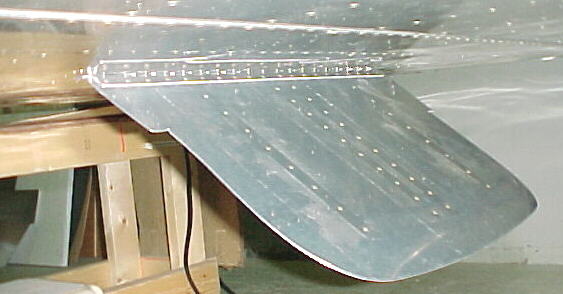
The pre-cover inspection has been completed by the MD-RA. Fuselage floors, soundproofing in place and main landing gear mounts installed. Some work done on wings, panel in planning stages as are fuel systems. Continuing on the fuselage.
07/24/06
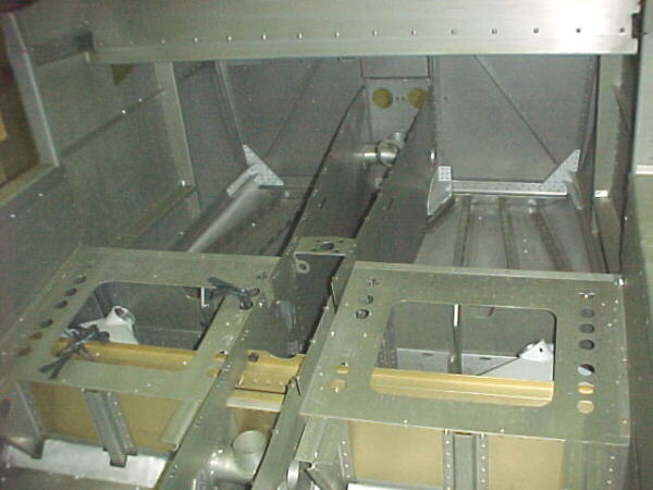
Work is proceeding in the tunnel on cooling lines and fuel system.
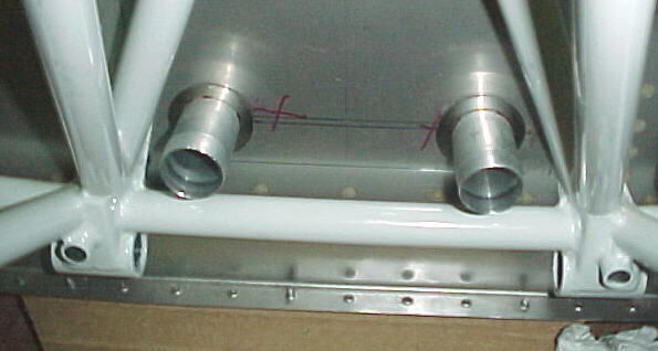
Coolant pipes with 304 stainless protection bushings installed through firewall
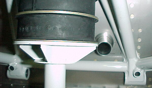
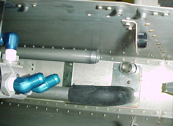
Pipe connections to radiator
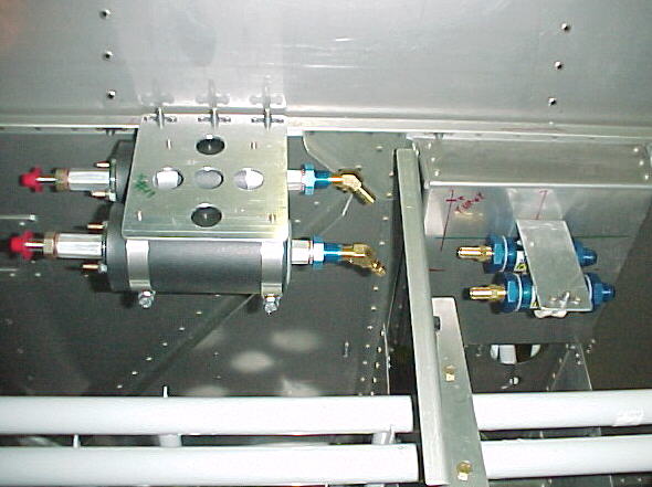
High pressure Walbro EFI pumps and Earls filters
Custom rad and cockpit adjustable rad flap on belly
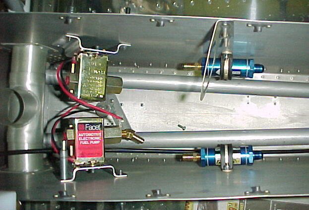
Low pressure Facet pumps and filters mounted in tunnel
07/31/06
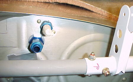
After many hours of pondering where to locate the fuel return fitting for the EFI in the wing tanks, I decided there was only one place for these to go where I had access to install the nut through the sender hole and where the line would not impact installation of the wing bolts, other fuel lines, or the aileron linkage. I used Earls Stato-Seals on the AN fitting to seal the tank without Pro-seal since internal access was impossible. Using a Unibit with a vacuum hose inserted through the sender hole to catch the chips, I drilled the two 9/16 holes. This was a much easier job on the RV6A with it's large, removable covers!
08/10/06
Work continues on the fuel and heating systems. The aluminum header tank is mounted and some of the lines have been run from the fuel pumps and fuel selector.

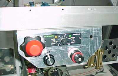
The sub panel mounting the engine/ prop controls is done. Throttle not mounted yet. We'll be flying the RV10 from the right seat again, just like the 6A. The main radiator flap control is far left, MT prop control center, SDS mixture knob lower left and wastegate control to it's right.
08/17/06
I had our interior made by FlightLine Interiors: http://my.execpc.com/~erdmannb/. They do excellent work and are helpful and easy to deal with. Highly recommended.
08/30/06
Our beautiful MT, 3 blade prop is finally in hand after a 9 month wait. Cooling system layout is all done, fuel system layout is all done up to the rear firewall connections, engine mount preliminary design is done, tubing to arrive shortly, turbocharger, intercooler, turbine discharge, oil cooler, cabin heat exchanger and ducting designs are roughed out awaiting the hung engine to refine. Things should start shaping up soon. That planned high capacity centrifugal blower intended for ground cooling and cabin heating duties will not fit as intended. Oh well, a saved 4 lbs. A smaller blower will be mounted behind the panel for the defroster duct.
09/18/06
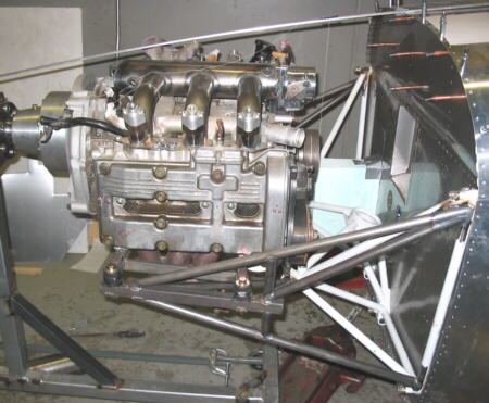
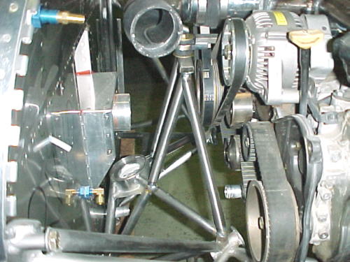
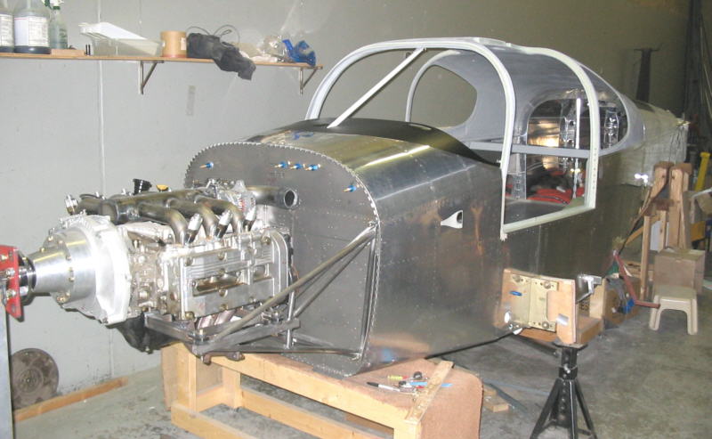
Work is proceeding on the EG33 engine mount. I spent a day modifying an old engine stand to be able grab the the engine by the prop flange. This allows complete access for fitting and welding components. It took half a day to align and level the airframe and engine. Many days were spent measuring and planning the layout of components for a clean, accessible installation. 4 pounds of tubing were cut off the Lycoming mount. The bed mounts are done and first tubes are now tacked in place. The engine is offset 1.2 degrees to the right, same as the Lyco. Barry Controls isolators are used.
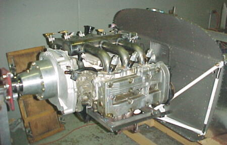
Custom stand places EG33 and redrive at correct height
09/21/06
The engine mount is all tacked up, ready for final welding in the jig.
09/24/06
Completed engine mount system weighs 8 more pounds than the Lycoming system.
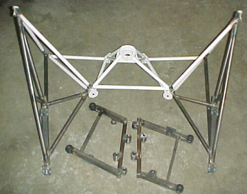
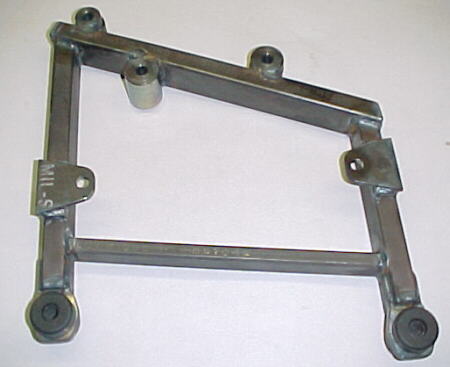
Bed mount for one side
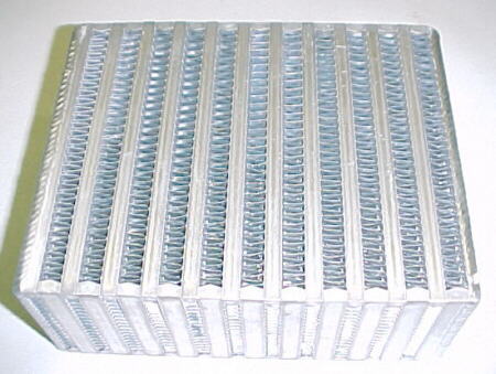
Bell intercooler core 6 X 7.5 X 3. We had excellent service from Bell. Highly recommended.
10/22/06
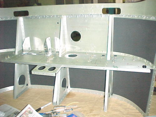
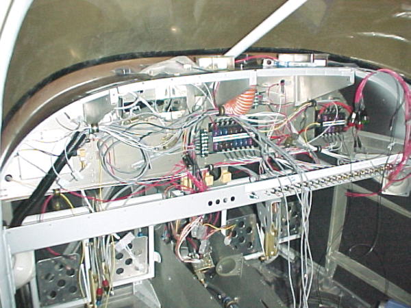
Work is being done on the firewall, engine, panel areas at the moment:
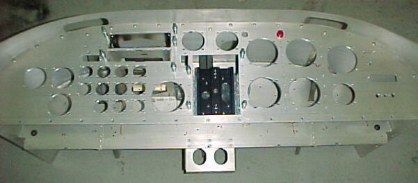
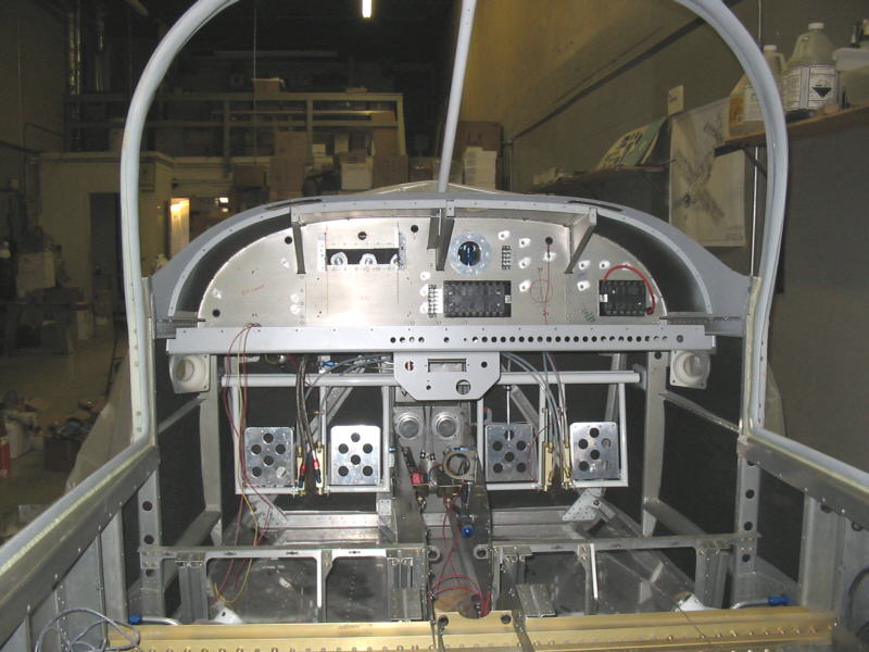
Panel cutouts and avionics racks mounted
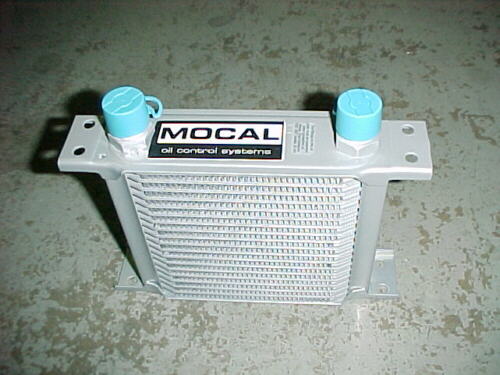
Mocal oil cooler will mount under reduction drive

One of the two Garrett T3 turbos
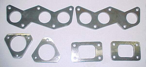
Turbo inlet and outlet flanges plus head flanges. A solid days work.
11/05/05
After much distress in finding a way to fit the turbos and intercoolers under the cowling, work is finally progressing.
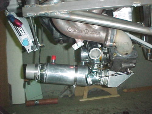
New heater box and connection to core
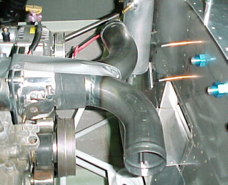
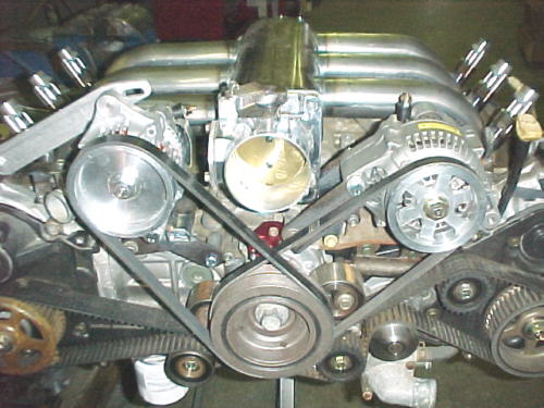
Magic tube to bring air from twin turbos to central 75mm Ford Motorsport throttle body
01/10/07
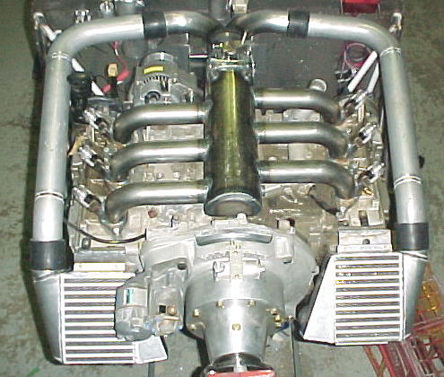
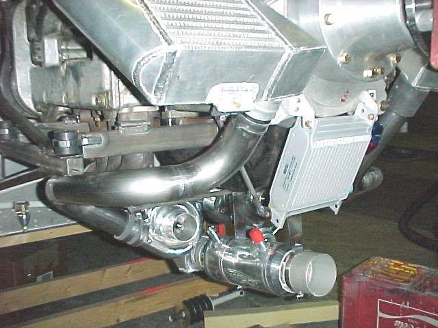
Intercoolers are welded up and mounted. Cabin heater and supplemental rad mounted, turbo scavenge pump mounted, oil cooler mounted, compressor discharge pipes done. Soon to be working on intercooler discharge pipes and backup alternator mount. Firewall forward stuff is getting closer to be done.

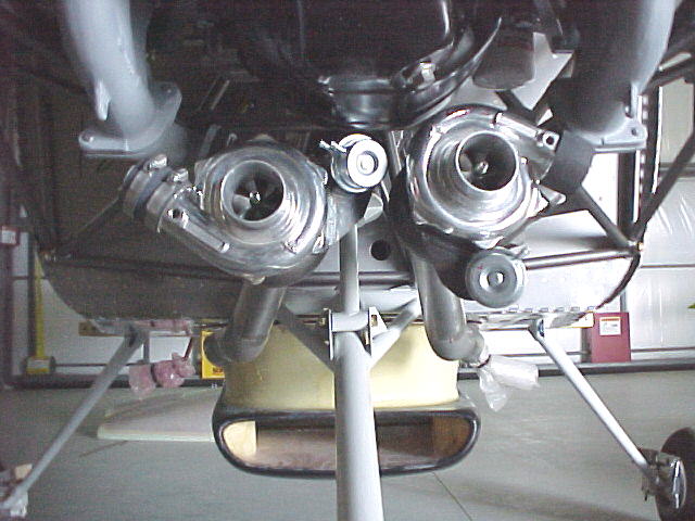
01/16/07
More pix of the engine with all the plumbing installed
03/05/07
Mounted up the second alternator and finished installing a lot of the cabin soundproofing.
03/28/07
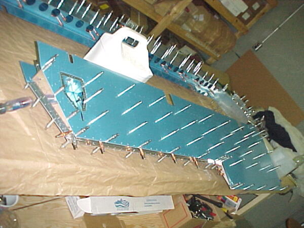
Front upper skin and cowling hinges are finally riveted in place. Riveting lower outer wings skins now.
04/24/07
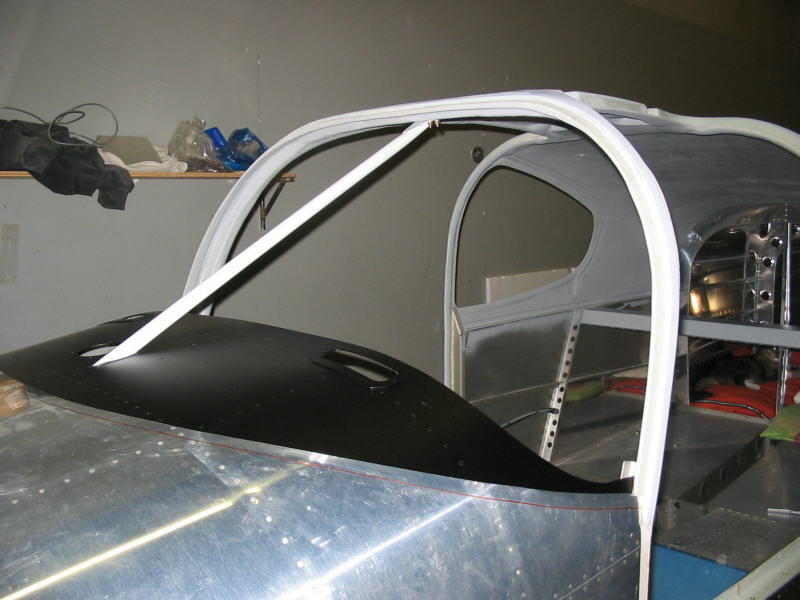
Lower wing skins now riveted, wing tips done. Working on trimming composite cabin top. This is an EVIL job.
05/21/07
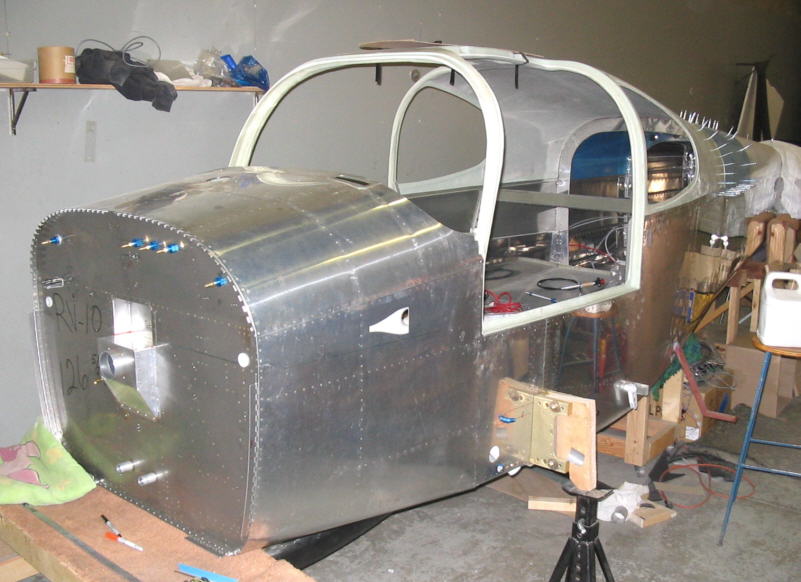
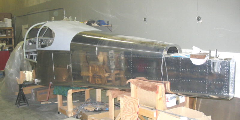
Cabin cover finally trimmed and fitted in place. Passing the canoe stage!
08/16/07
The cabin cover and mid upper skin are now bolted and riveted in place. Work was delayed waiting for some custom parts to arrive and be fitted before closing the aft structure in with the skin. In the meantime, certain small parts were designed and machined.
5th attachment point added for engine due to concern with possible whirl mode issues
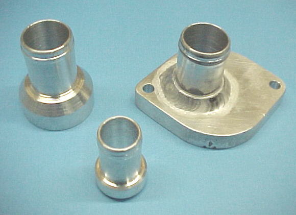
Various water connection parts machined and welded including the water pump inlet connector to eliminate the thermostat
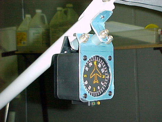
PAI vertical card compass mount with triple shock mounts
09/01/07
I added a curved guide vane to the radiator duct to aid in turning the airflow without separation to the rad face.
09/11/07
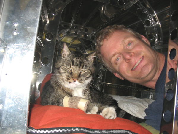
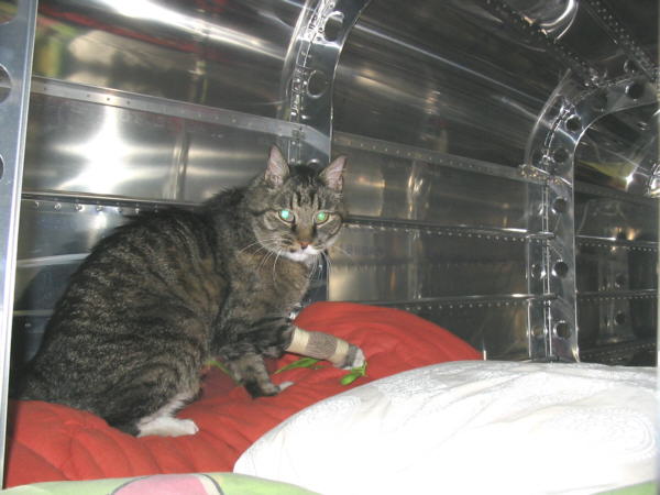
Finally have upper mid skin riveted on so most riveting with the gun is over with. Our shop cat, Freeway has been assisting with final assembly in the confined rear fuselage.
Will be test fitting the wings next week hopefully.
10/01/07
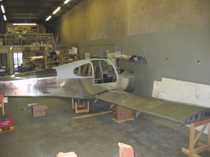

Wings are now mated to fuselage. Very impressed with how easy this was compared to the 6A. Bravo Vans!
10/19/07
With most of the metal work now done, I'm working on the engine now. The Subaru EG33 is a beautiful piece of engineering, perhaps the nicest engine I've ever worked on. This is saying a lot. I've built over 200 engines professionally over 30 years from almost every manufacturer. The EG33 design, metallurgy, machining and workmanship are outstanding for a production based engine with great attention paid to the details.
The EG33 is an all aluminum 3317cc, horizontally opposed flat six. Valvetrain is by double over head cams in each head, activating hydraulic bucket type lifters which act on 4 valves per cylinder in a pentroof combustion chamber. Compression ratio is 10.0 to 1. The intake ports are large and well shaped for excellent flow. Valves are 36mm on intake, 32mm on exhaust. The engine is fitted with 7 main bearings and a fully counterweighted, forged crankshaft.
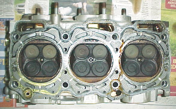
Cylinder head.
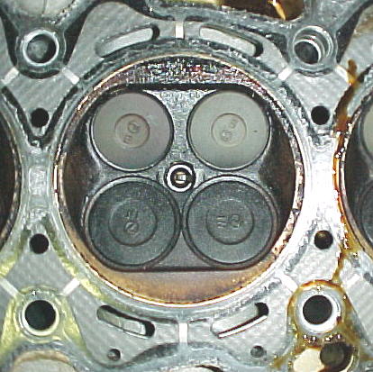
Compact combustion chamber. Note metal straps to support fire ring. Nice touch.
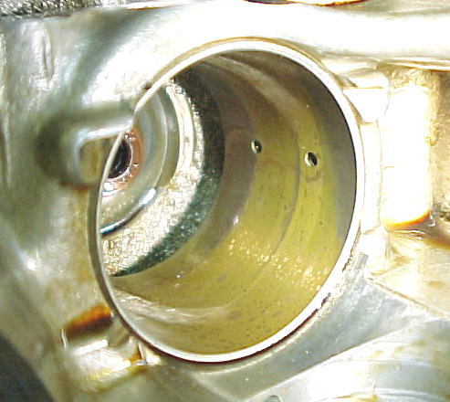
Thin wall bronze bucket insert with internal oiling. Most engines run the buckets directly on the aluminum head with no oiling.
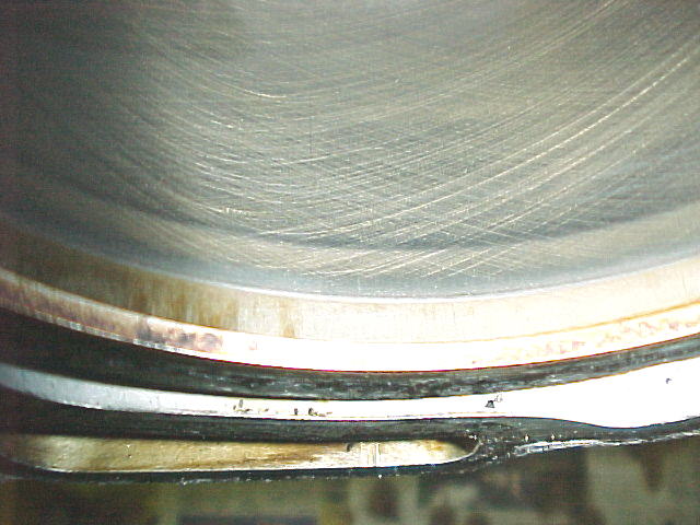
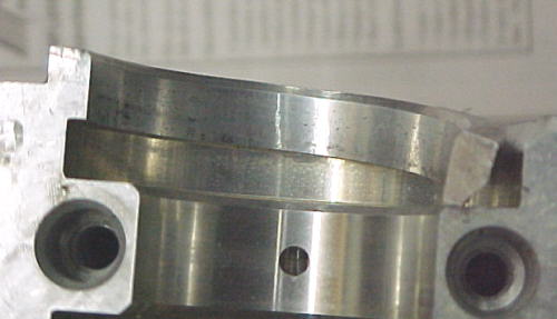
Think auto engines won't last. Here are the factory honing marks on cylinder running past top ring travel after 80,000 miles.
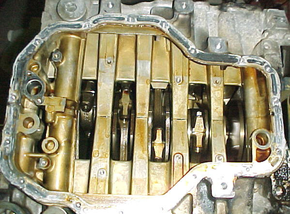
Shot of crancase bottom. Note ultra stiff cross bolted design with 7 main bearings.
Holes in block to withdraw piston pins. Annoying but allows a stiffer cylinder/ block assemby.
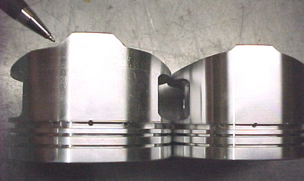
The EG33 uses cast iron cylinder sleeves which are cast in place when the aluminum block is poured. The open deck design uses full length central and end support of the cylinder walls to minimize movement and walking of the bores unlike many other open deck designs. The heads are bolted to the block with long bolts threaded into the crankshaft web area to eliminate deck distortion. So far, there has been no measurable wear on any parts examined. Plans are to replace the stock cast pistons with JE forged ones. The rest of the engine will remain stock. The pistons project above the block deck about .020 at TDC. When combined with the head gasket thickness, this allows a proper chamber quench dimension of around .020-.025- most engines effectively negate this by using too much piston to chamber clearance here. The casting work on the heads, block and valves cover is outstanding. Truly works of art.
12/01/07
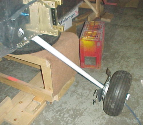
The engine is all apart and cleaned up. Awaiting pistons and other parts. In the meantime works proceeds on other parts. I had to polish down one main gear leg as it was about .001 out of round and would not go into the mount. I also had to remove the right main gear mount as it was totally warped because it did not fit the airframe well. I drilled out some of the holes a bit and shimmed the back side to correct its location. That done, both legs were finally fitted. Wheels, tires and brakes were assembled and installed on the legs. The next problem was that the axle nuts would not thread on properly. Turns out they were defective and Van's is sending some proper ones to fix this somewhat common problem.
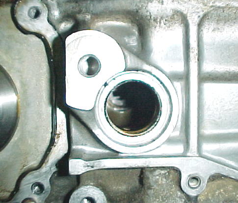
Switching to the nose wheel, we encounter several more problems. First is that the Van's supplied wheel does not allow the valve stem to properly clear the fork. Matco will exchange these for the proper one at minimal charge. Van's also supplies new U-1023 aluminum wheel spacers after many found serious problems with the original thin walled stainless spacers.
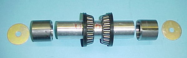
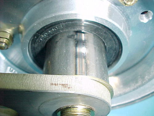
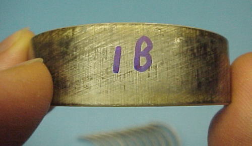
Unfortunately these do not solve the problem at all and it is a mystery on how either setup could be approved by any engineer at Vans. The problem with the thin walled stainless spacers was that they had a tiny contact area with the curved ID of the bearing cone as seen in the two photos below:
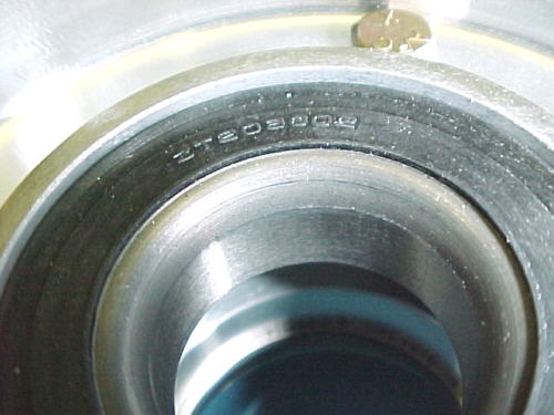
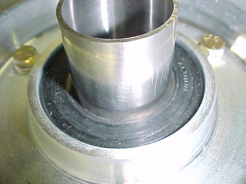
It took nothing for the spacers to start spinning against the inner race. This also meant that is was spinning against the fork and cutting into it, not to mention losing any preload on the bearings leading to massive play.
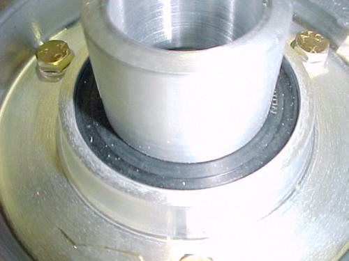
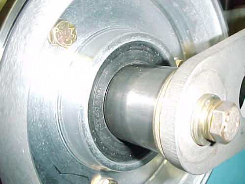
The thicker aluminum one is no better and shifts the problem. Due to its larger wall thickness, it actually sits on the rubber seal! This throws any preload out the window and allows the spacer again to spin, grinding on the fork and causing bearing slop again. Wheel bearing assemblies must always have proper metal to metal contact for proper operation.
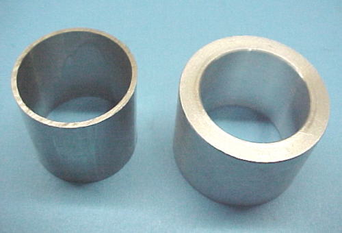
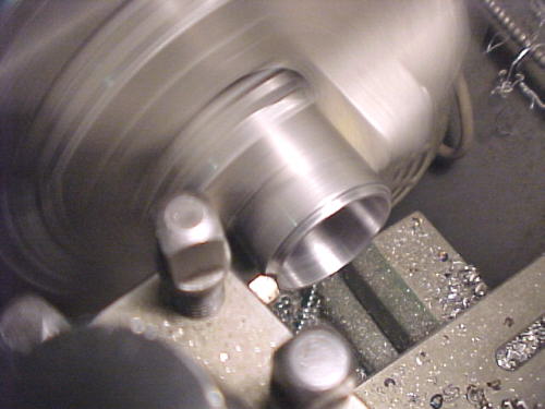
I tried to find a sealed bearing with a flat inner face but was unsuccessful. I therefore machined 2 new steel spacers from 1.5 inch tubing. These have a curved surface to mate with the inner bearing race.
I also installed a big AN970-6 washer on each end to prevent damaging the fork if something does come loose. I had to machine .118 off the center spacer for these to fit correctly. By carefully assembling and measuring, I established that a .004 preload was about right on the bearings and adjusted the side spacers to get this.
New assembly
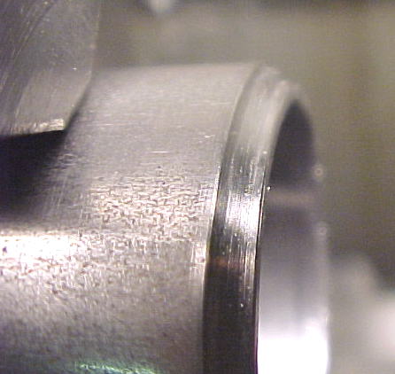
Proper fit of spacer sits on cone and clears seal rubber
 Fully assembled
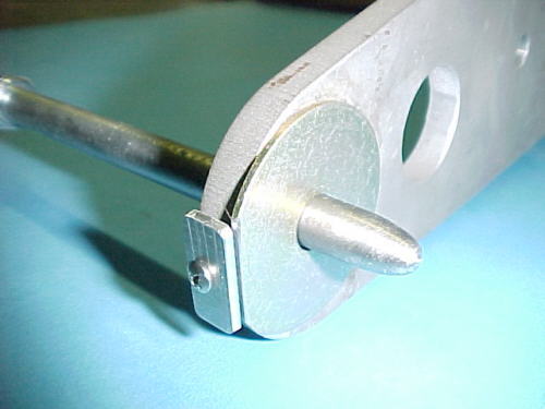
I decided to add an anti-rotation device for the washers and filed a flat on the washer, made small plates from .090 aluminum and drilled and tapped the fork ends for 4-40 screws. This should help limit any sleeve rotation damage to the sleeve and bearings.
12/30/07
Been working on the engine mostly

Oil pump checked out mint
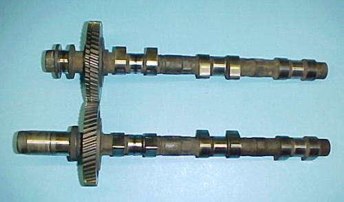
Camshafts were also mint
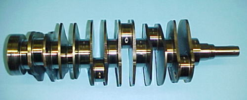
Forged alloy steel crank, nitrided, rolled fillets
Short stoke design allows for generous crankpin overlap for strong, lightweight crank
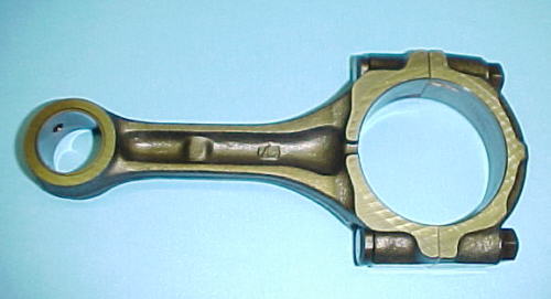
Forged rods

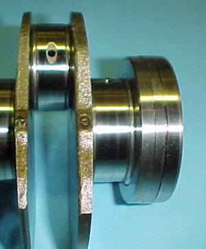
Main bearings in very nice condition after an estimated 2100 hours
Bearings marked for position to be re-used
JE forged pistons required reworking of skirts to clear crankcase webs
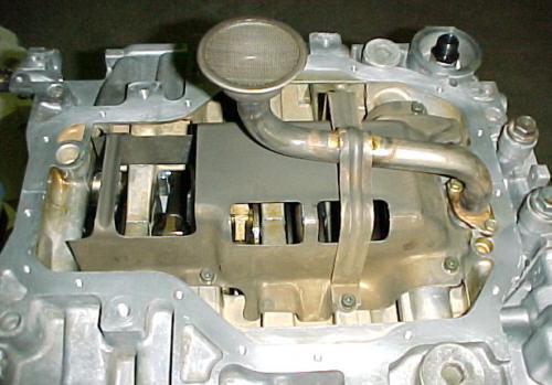
Factory windage tray and oil pickup
01/21/08
Bad news, the courier company dropped my cylinder heads and wrecked one. Ordered a new one from Subaru. Good news is that engine mount and nose gear is now fitted. Almost ready to put the plane on its gear.
Arrrggghhh!
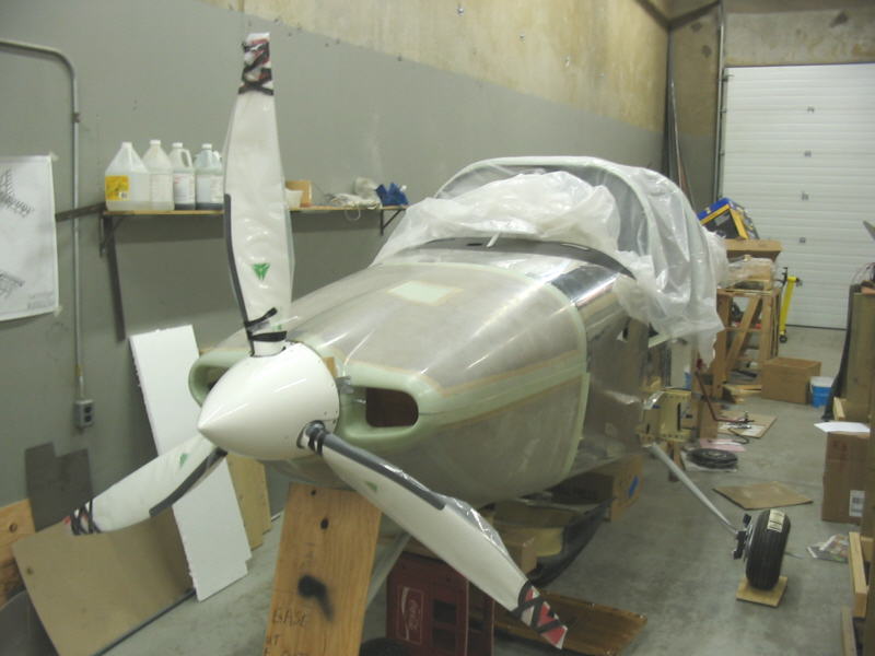
03/06/08
Engine is finally together and back in the aircraft which is sitting on the gear now. MT prop is temporarily fitted as well.

04/08/08
I'm starting to fit the cowling now.
05/22/08
The cowling is now mostly fitted and I spent many hours fitting a now oil filler access door to the cowling to suit the different location on the EG33. Dealing with the honeycomb in this location made the job quite time consuming.
06/15/08
Working on doors now.
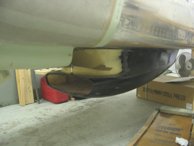
Rad scoop in place with cowling
08/08/08
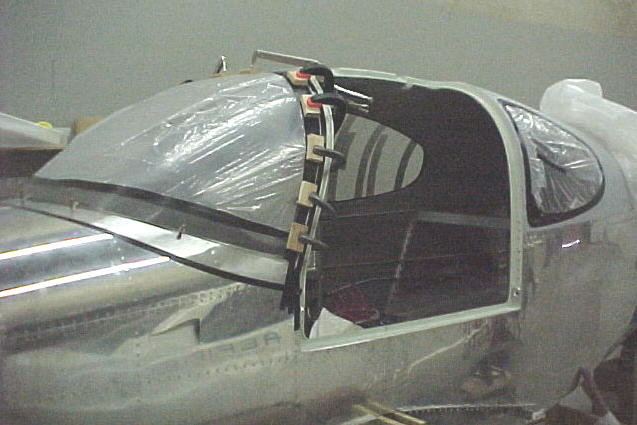
The doors all all done now except for filling the *&^$##$% pin holes, painting the inside skin and gluing in the windows. These were a ton of work. Once these tasks are completed, I just have to glue the side pax windows and the windshield in and most of the major constrution tasks will be done.
08/17/08
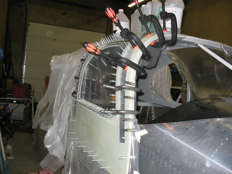
The windshield is finally bonded on, side pax windows too and the main side windows are bonded into the doors. Some filling and sanding to do around the edges and the bottom windshield fillet but at least the main part is done. I used Flox and West System for bonding all of them in as shims were required. The Weld 10 would have been a pain to get applied in the thickness required before it set IMO.
10/03/08
I've spent the last 6 weeks finishing off filling and sanding around the windows, windshield and finishing odd jobs on the fuselage. The doors have been fully fitted and work well. The stab doubler is riveted in place and I finished some interior painting of the door sills and flox line. The prop and PSRU have been removed in anticipation of transporting the fuselage out to the airport in a couple weeks. Finishing the project will be delayed due to lack of space for about 6-7 months until the new hangar is done but I'll plod along on filling and sanding fiberglass parts, wiring, systems and possibly priming and painting of some of the smaller assemblies. Glad to be at this stage anyway.
The cabin top, doors and windows were nothing but a big pain and there was nothing fun about any of this part of the RV10 project. I'd prefer to do more sheet metal work and less fiberglass work which is tremendously time consuming.
Time to date on the project is 1201.5 hours.
03/05/09
With the airframe now in storage in the hangar awaiting a larger hangar to be built so assembly can continue, I'm now working on wiring, waiting for warmer weather so I can take fiberglass parts outside for filling and sanding. Progress will be slow for the next few months.
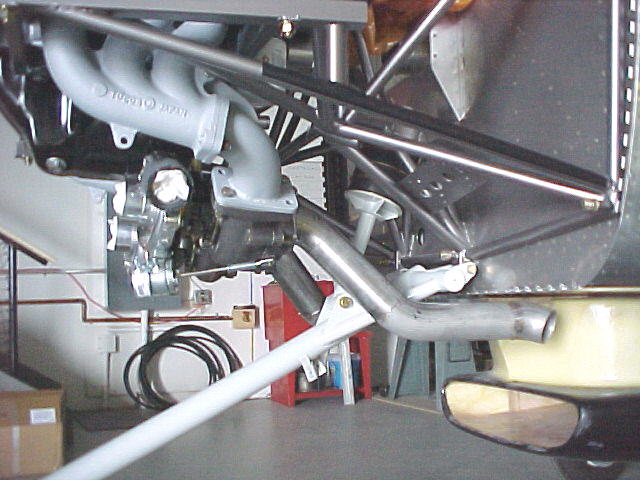
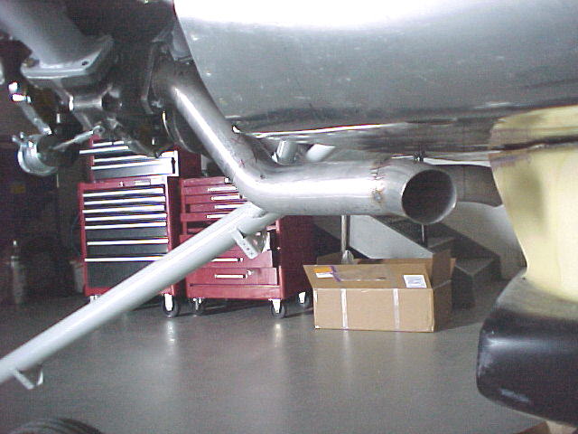
06/06/10
Finally back to work on the project. Have been fabbing up the turbine outlet pipes from 2.25 inch 321 stainless tubing. Photos below show them tacked up in place. Will be adding O2 sensor bosses and some support stays shortly.