

05/22/99
This article details the complete fabrication process on a custom intake manifold for a developmental Mazda RX7. The basic design can be easily adapted for almost any engine design. Tools needed to fabricate this part would include a drill press, lathe, bandsaw, hole saws, files and a TIG welder. This manifold was constructed from mild steel for ease of assembly but it could also have been made from aluminum.
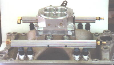
Basic Design
This plenum type design uses a single throttle body attached to a plenum with separate intake runners for each port. Port type injectors are mounted in each runner.
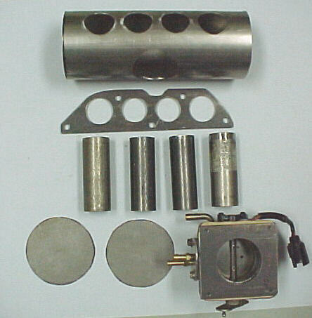
Head Flange
The main flange which would be bolted to the cylinder head in the case of a piston engine, is made from 1/4 inch steel plate to reduce warpage during welding. An intake manifold gasket can be used as a guide to trace the flange outline and mark the port and bolt holes. The flange plate can be cut out using a bandsaw or plama arc torch. Bolt holes can be drilled on a drill press. Intake runner tube holes can be done with a hole saw or plasma arc if they are not round. Try to design the port holes so that the ID of the tubing used for the runners is the same of that for the finished port size in your head. The runners should be spigotted inside the flange hole for ease of jigging.
Intake Runners
Runners are made from .050 to .065 tubing. Runner lengths can be adjusted within the space constraints to help boost torque within the desired range. Short runners are good for high rpm torque as in a racing situation. Long runners are more applicable for street use at lower rpms. For most street engines, try to keep the length from the end of the runner to the valve at least 9 inches long and preferably longer. Available space usually limits this dimension when using straight runners so curved runners using 90 degree mandrel bent tubing can sometimes be used to increase the runner length. As applied to engines with oval or square ports, you will have to form the tubing into the port shape which is considerably more complicated. Tubing should be cut off at precise lengths with a tubing cutter and carefully deburred. For maximum airflow, tapered runners with velocity stacks inside the plenum can be made if you are capable of this type of work. This is very time consuming but this design shows a 20-25% increase in flow over straight tubing runners.
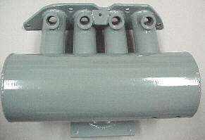
Plenum, End Plates
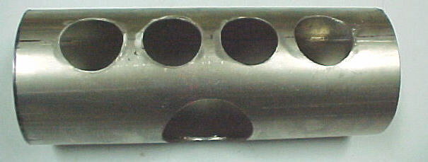
Depending on engine displacement and the throttle body used, the intake plenum is usually constructed from .065 wall exhaust tubing in either 3 inch for engines under 1600cc or 4 inch for most other engines. Holes must be cut in the plenum tubing with hole saws for the intake runner tubes and in the case of a side mounted throttle body, for the throttle body tube also. The throttle body may also be placed on one end of the plenum in place of an end plate, depending on component layout. Our RX7 manifold used 4 inch tubing. The plenum should be made at least 2 inches longer than the dimension of the front to rear outside intake ports to allow better airflow into the outer ports. Also plan for any vacuum taps for brake boosters or MAP sensors etc. at this point.
End Plates, Throttle Body Plate
End plates cap the plenum ends and are made from .050 to .065 plate stock. Cut them out with a bandsaw or plasma arc. Make them about the same size as your plenum tubing OD. If you plan to put the throttle body on one end of the plenum, this end cap will need to be made from 3/16 to 1/4 inch plate to allow for tapping of threads to hold the TB as well as have a hole cut the size of the outlet TB bore. If the throttle body is to be mounted as in our RX7 manifold, use 1/4 plate for the TB flange. We like to tap right into the plate with fine threads for maximum strength.
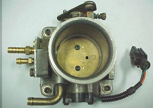
Throttle Body
Throttle body choices are numerous. One should be selected which can flow the desired amount of air and fits within the space limitations. Thought should be put into the ease of connecting either an air filter or turbo plumbing to it. Too large of a throttle body for street use will often mean very sensitive "tip in" throttle response which could be annoying. There is also no need of a 3.5 inch TB when your turbo plumbing is only 2.25 inches. Getting a throttle body with a potentiometer type TPS already installed will save time and trouble. For many applications, the Ford 5L V8 and 4.6L DOHC throttle bodies work well. They are cheap, available and relatively compact. Ford Motorsport and Edelbrock make larger sizes in 5mm increments. The 4.6L TBs are very compact and have a minimal amount of extra garbage on them. All Ford TBs have potentiometer type TPSs also. Ford Explorer 4L throttle bodies can be ordered from your dealer. These are relatively inexpensive and are 65mm with minimal garbage on the outside. Put some thought into a throttle linkage at this point also.
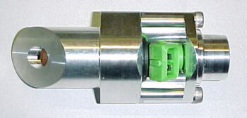
Injector Bosses
We usually make these out of 1 inch bar stock. We like to seal the vacuum side of the injector with a 5/8 ID- 3/4 OD O-ring slid over the nose of the injector body. This will work on any standard injector. You can pull off the stock O-ring and pintle cap. Bore the bar stock to .640-.650, straight through. This allows a slight air gap between the boss and injector to reduce heat transfer and fuel boiling. A .740 counterbore, .040 deep is machined at the end for O-ring retention and sealing. We usually cut off the bosses at 45 degrees so that they are about 1.35 to 1.5 inches long. This is a good entry angle for many injectors into the runner and is an easy angle to saw at.
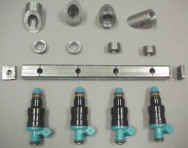
Fuel Rail
The fuel rail is usually made from 3/4 square tubing with a .050 to .065 wall. This shape allows much easier drilling and jigging. 1/4 inch holes can be drilled at the port spacing interval. Over top of these holes will be welded the upper O-ring bosses machined from 3/4 bar stock. These will usually be about 1/2 an inch long and have a .540 to .545 hole drilled for the O-ring to seal on. Carefully chamfer the entry side for easier O-ring fitment. End caps for the rail are made from 1/4 plate and tapped for 1/8 NPT fittings. For a more detailed description on building a fuel rail, go to the article on our tech page.
Assembly
Once all of the pieces are cut out and deburred, clamp the head flange to a scrap head if possible to reduce warpage. Carefully jig the plenum and runners to the flange and measure for straightness. Tack weld the pieces lightly and re-check for straightness. You should still be able to move things around a bit at this stage. Tack the opposite side of each joint and re-check again. Once you are satisfied, TIG weld all of the joints. Weld on your end caps and TB flange. Let everything air cool.
Now you must cut holes in the runners for the injectors to poke through. Scribe a line across the runners where you want the center of the injectors to be. Now intersect each mark on the runner with another line down the center of each tube. Punch mark and drill a 1/4 hole. Now drill straight through with a 1/2 inch drill. Once you pierce the tubing, slowly lean the drill over at 45 degrees to oval the hole. The injector bosses will be positioned over these oval holes so make sure before starting that you have enough room around the boss to the flange that you will be able to get the welder in there. Assemble the injectors into the rail and slide the bosses over the injectors. Carefully align the assembly so that the injectors are dead center through each injector hole in the runners. Clamp in position and re-check. Lightly and quickly tack each boss in position. As soon as this is completed, either pull the injectors out or water quench each tack to avoid heat damage to the injectors. Once you are satisfied that everything is straight, finish welding the bosses without the injectors in place. Be aware that the bosses must be welded in very straight and at the same depth for proper sealing.
Finishing
You can weld on bolt down tabs on the fuel rail and attachment points for the bolts on the manifold. A couple of long, 1/4 inch bolts usually suffice here. The manifold can now be thoroughly cleaned with soap and hot water, then lacquer thinner. A good quality engine enamel can be used to finish or better yet, get it powder coated.
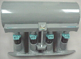
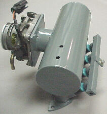
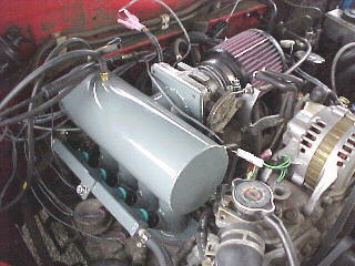
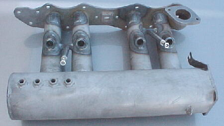
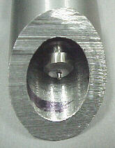
Here are some photos of an intake manifold for a Toyota 20R for more ideas:
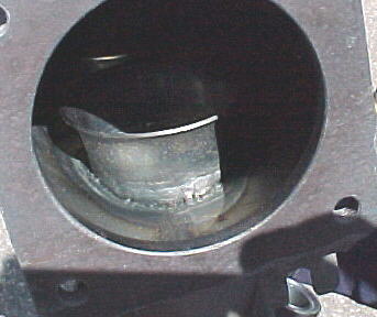
Note internal velocity stacks
11/15/00 update
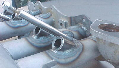
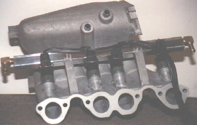
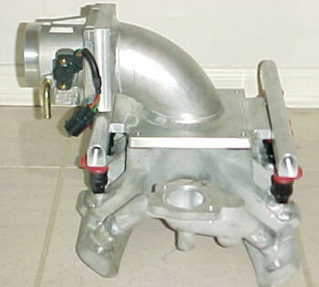
Here are a couple of manifolds modified to accept EFI type injectors through the use of weld-in bosses:
Update 01/21/05
For info on a Subaru EJ22 intake manifold project:EJ22 Intake Manifold
For info on a Subaru EG33 intake manifold project:EG33 Intake Manifold
New injector bosses available with steel or aluminum bases, accepts 1/8NPT fuel fitting