Last update Feb. 11/24
This page is primarily for automotive systems though the basics apply to aviation systems as well. Please find documentation for tuning aviation systems near the bottom of the Aircraft Page:
Aircraft

Shown below is the hand-held LCD programmer which plugs into the ECU via a six foot cable. This unit takes the place of the laptop used on most other programmable systems. The PGU uses a membrane switch keypad. A fast forward scrolling button to quick scroll at 20 frames per push.
Updated with new programmer graphics design Feb. 21/14
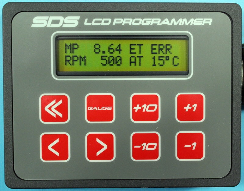
This shows the programmer in gauge 1 mode, displaying rpm, manifold pressure, engine temperature and intake air temperature. Note that the engine temp show ERR. The ECU will display this error code for various sensor failures allowing instant diagnosis of system problems.
The programmer contains seven push-buttons used to select and change functions. The < and > buttons allow the user to scroll left or right through the parameters. The +1, -1, +10, and -10 buttons allow the user to increase or decrease the value in the lower right of the LCD window. The value may be any number between 0 and 255. The larger the number, the more fuel that will be injected at that parameter or range.
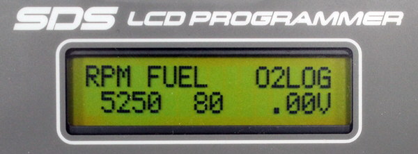
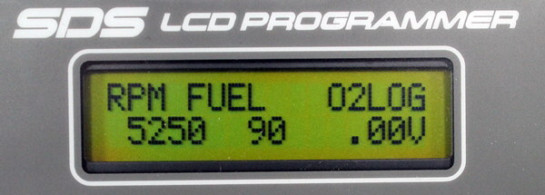
The picture on the left shows the RPM FUEL parameter at 5250 rpm with the fuel value set at 80. By hitting the +10 button once, the fuel value can be increased to 90, as shown in the second picture picture, thus richening the mixture at 5250 rpm. Also note on the right side of the screen, the built in AFR dats logging display which allows you to log AFRs at wide open throttle to quickly set rpm fuel values.
Holding down any of these six buttons for more than 2 seconds permits you to advance ranges or values at the rate of 8 per second until the button is released.
The gauge button permits instant access to gauge 1 mode which displays manifold pressure, RPM, air temperature and water temperature.
Gauge modes allow the user to see where the ECU is currently operating to aid in tuning. Pressing the GAUGE button a second time returns the LCD window to its previous parameter and range to allow speedy adjustments without scrolling through the entire menu.
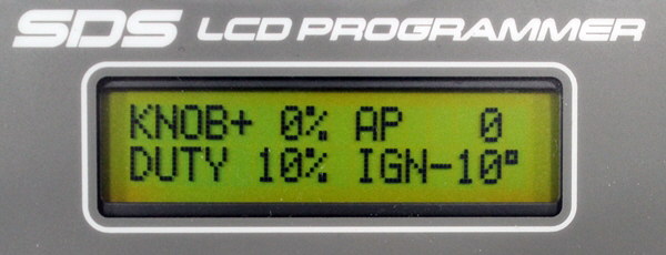
Gauge 2 mode, shown above, displays the mixture knob position, injector duty cycle, acceleration enrichment and ignition timing.
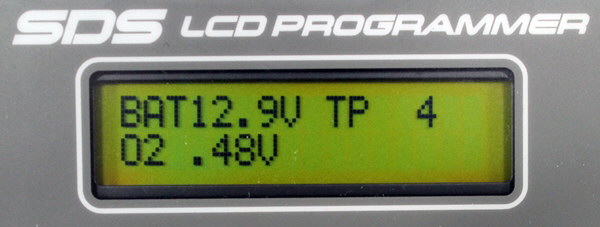
Gauge 3 mode, shown above, displays battery voltage and throttle position for setting fuel cutoff limits plus optional fuel flow.
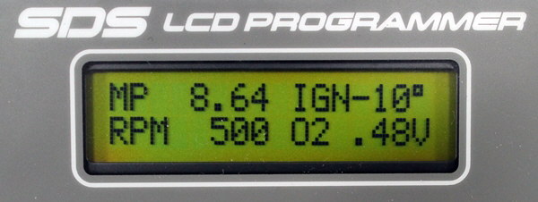
Gauge 4 mode displays rpm, MAP, O2 voltage or AFR and ignition timing
The programmer permits access to all fuel and ignition parameters. Fuel and ignition timing with regards to manifold pressure or throttle position is adjustable at 64 steps, rpm fuel and ignition timing in 250 rpm increments, acceleration enrichment, cold start, warmup, knock sensing, fuel cuts, closed loop and various relay drivers are all adjustable through the LCD programmer.
Some of the other programming function windows are shown below:
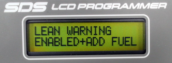
This will enable a lean mixture warning and the ECU will automatically add extra fuel to protect the engine based on the optional wideband O2 sensor input.
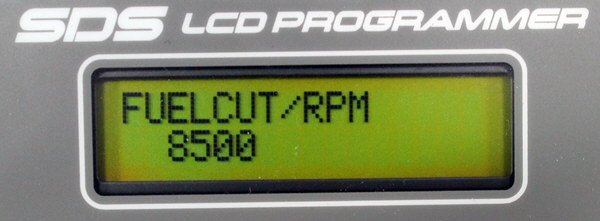
This shows the fuel cut rev limiter set at 8500 rpm, again to protect the engine.
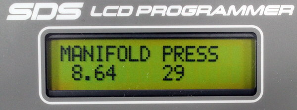
This is one of the manifold pressure windows showing 8.64 psi boost and the fuel amount is 29.
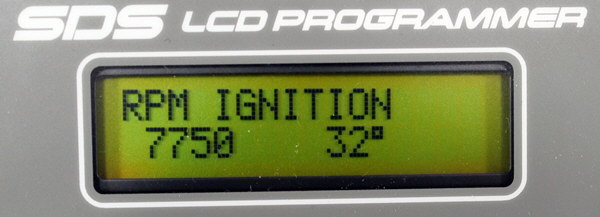
This shows how ignition timing is set with rpm. At 7750 rpm, we have 32 degrees of timing.
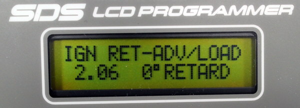
We can modify rpm timing with advance or retard related to manifold pressure. Here we show at 2.06 psi boost, we want to retard timing 0 degrees.
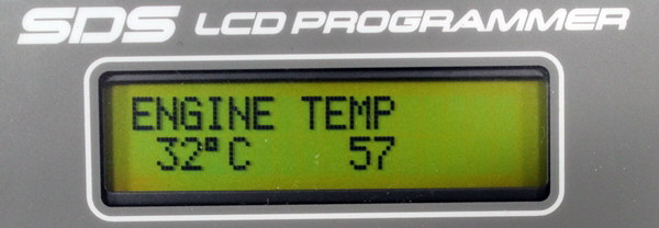
This shows warmup enrichment. At 32c coolant temp, we are adding 57 for fuel. You have 32 temperature points to program. This acts like a choke on a carb.
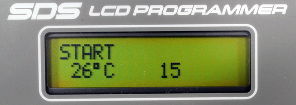
This shows the start enrichment used for cranking and the first few seconds of idle. We are adding 15 for fuel at 26C coolant temp.
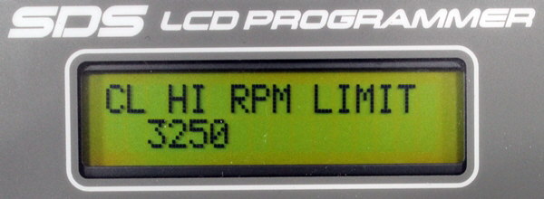
This shows one of the closed loop limits which defines where the ECU will operate automatically in closed loop from the O2 sensor input. We cut off operation here above 3250 rpm.
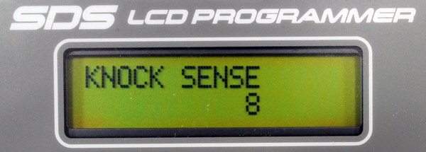
Here we show the knock sensitivity setting. This allows fine tuning of the knock sensor input.
There are many other windows which allow you to adjust the full range of the ECU to suit your particular application. This is just a short example of the control you have using the programmer box and how simple it is to make changes without the need for a laptop.
Programming Basics
Most programming is done with the programmer in Gauge 1 or gauge 4 modes. This allows the operator to see where the ECU and engine are currently operating. By using the mixture knob and feeling where the engine runs rough or with the aid of the recommended air/fuel ratio meter and the AFR date logging feature, adjustments can be made at each step until a satisfactory engine map is generated. When properly programmed, the ECU will deliver the correct air to fuel ratio under all conditions for proper running. Units are shipped out with a full map installed, taking into account engine displacement and injector flow rates. This normally permits the engine to be started up with minimal problems. From this point, the operator can start fine tuning the system by following the detailed installation and tuning manuals provided.

Informational and Tutorial Video Links
Basic programmer function, gauge modes, RPM Fuel, MAP Fuel parameters
Basic programmer function Part 2
Installation and Tuning Manuals
EM-5 Installation and Tuning Manuals (Automotive)
PDF versions below approx. 1Mb file size.EM-5F supplement for 4F and 6F manual PDF
See Aircraft Page for aviation manuals
EM-4 Installation and Tuning Manuals
EM-4F supplement for 4F and 6F manual PDF
EM-3 Installation and Tuning Manuals
For the EM-3 we recommend using the EM-4 manual, however there are a few differences.
The EM-3 knock sense parameter will only adjust from 1 to 16, whereas the EM-4 can adjust from 1 to 32.
The EM-3 cannot support the new nitrous retard, and A/C aux input features.
The EM-3 does not have a 5 volt tach output on the main harness connector.
Otherwise programming, tuning and hookup are the same on both models, and since the EM-4 manual has been rewritten
it is the best choice for the EM-3 owner to use.
EM-2 Installation and Tuning Manuals